Customize Gear Skiving for Precise, Efficient Gear Cutting
February 16, 2024

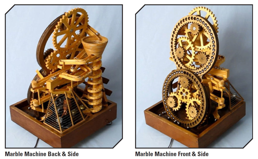
Built with 16 gears, this entertaining device is called a marble machine because it usually transports glass marbles. Ron Walters, though, prefers to use 5/8" ball bearings. Unlike glass marbles, the ball bearings don’t chip despite constantly knocking against each other.
Ron Walters started building his wooden machine as a pastime after his foot surgery. Months later, the retired mechanical engineer had an entertaining device that featured 16 gears and could move ball bearings at a rate of 7,200 per hour.
The device, called a marble machine, holds 75 ball bearings, weighs 30 lbs., stands 30" tall, has a base 19" square, and includes two ring gears, each 14.5" in diameter.
All 16 gears move the ball bearings the 30" from the bottom of the machine to the top. Moreover, the two largest gears actually carry the bearings. They are identical ring gears, and they carry bearings in holes carved in their rims.
Starting at the machine’s base, each bearing rolls into a hole in the rim of the lower ring gear. The gear rotates clockwise, carrying its bearings upward. The bearings stay in their holes because the ring gear has a backing. The backing is circular and stationary, but with a hole at its top. So, as the lower ring gear rotates, each of its holes reaches the backing’s hole. When a gear hole lines up with the backing’s hole, a bearing transfers from the lower ring gear to the upper one.
Rotating counterclockwise, the upper ring gear has an identical backing with an identical hole at its top, which is also the top of the machine. So, when a gear hole lines up with the backing’s hole, a bearing rolls out of its hole and through the other hole.
Now at the top of the machine, a bearing starts its way back down by first rolling into a vortex funnel that looks like a flower pot. The funnel has three holes: one in the bottom of the funnel, two in the wall of the funnel. The two in the circular wall are diametrically opposite each other. If a bearing goes through the bottom hole, it rolls down a spiral track. At the bottom of this path, the bearing rings two old, brass telephone bells.
If a bearing goes through one of the holes in the wall, it rolls back and forth, back and forth down a zigzag track. If it goes through the other hole in the wall, it rolls to a flip-flop mechanism that directs the bearing to one or the other of two paths. One path leads to the machine’s xylophone, six bars of rosewood. “Apparently, they use rosewood in real xylophones,” Walters said.
The other path leads to a divide-by-three mechanism. This mechanism works like an automatic trapdoor. When three bearings are on the free end of the mechanism, their weight causes the end to drop like a trapdoor opening in a floor. The bearings then roll down a track and fall into a dump-o-matic. This wooden cup can hold up to 12 bearings. Once 12 accumulate, their weight causes the cup to tip over, dumping the bearings onto the machine’s base.
In total, a bearing can take one of four paths: the spiral path, the zigzag track, the xylophone path, or the dump-o-matic. Which path the bearing takes is up to chance. However, Walters observed the machine and figured out there were tendencies. Almost 10 percent of the bearings reach the bottom of the funnel and roll down the spiral path. About 50 percent take the zigzag track, and about 40 percent roll to the flip-flop mechanism.
At the end of each path, a bearing reaches the machine’s base. The base is sloped so the bearings roll back to the front of the machine, where they start a trip to the top all over again.
All of this motion can be seen in three videos on Walters’s YouTube channel, Ronald Walters. The main video can be viewed here or below.
Also, all of this motion is possible because the two ring gears rotate at the same speed, cleanly transferring their bearings. The identical speeds result from two identical timing gears. These gears are connected to the machine’s two driving pinions: a pinion of the lower ring gear and a pinion of the upper ring gear. The two pinions are powered by a 110-volt shaded-pole gearmotor.