3D Scan-Based Reverse Engineering of Differential Bevel Gears
Inter-wheel differentials utilizing straight bevel gears are commonly used in the automotive industry to accommodate the relative speed differences between wheels during cornering. These mechanical systems have been integral to vehicle design for over a century, often carried over from one project to another. Consequently, the expertise and knowledge surrounding these systems can sometimes be lost, leading to challenges in design continuity and innovation. This gap in knowledge underscores the necessity for developing effective reverse engineering methods for differential gears. Such methods are essential not only for recovering lost design information but also for conducting comprehensive analyses of competitor products. The advent of advanced 3D scanning technology has revolutionized the field, providing new opportunities for the efficient and accessible reverse engineering of complex components. This study aims to propose a robust reverse engineering methodology for straight bevel gears, especially for those found in inter-wheel differentials. By leveraging 3D scans of sun and planet gears, an innovative approach to accurately reconstruct the macrogeometry parameters of these critical mechanical systems is proposed. The rebuilt geometry was used to create a measurement grid for flank topography evaluation. These measurements were used to extract the contact ease-off, thereby revealing the complete macro and microgeometry of the previously unknown differential gears.
3D Scanning
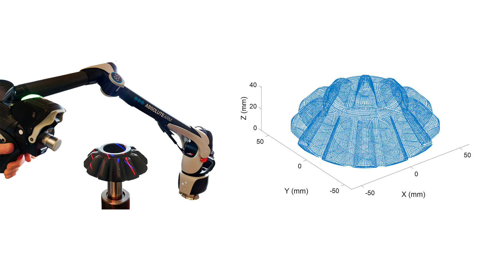
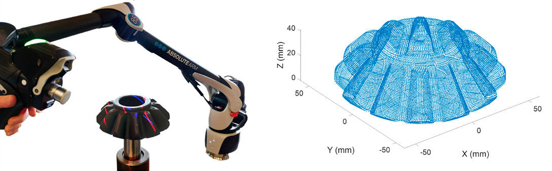
The method described in this paper is specifically illustrated through the analysis of a planet gear from a commercial vehicle inter-wheel differential. It is assumed that the original geometrical parameters of this design are unavailable and required for further studies. The process begins with 3D scanning of both the sun and planet gears. The planet gear was scanned twice: first while supported on its back face as shown in Figure 1 (left) and then inverted upside down. Each scan generated approximately 30 million data points. These scans were subsequently merged and exported in STP format, resulting in a refined dataset containing over 40,000 points. The Cartesian coordinates of each node defining the 3D shape of the part were then extracted, as shown in Figure 1 (right).
Figure 1—3D scanning of planet gear (left) and point extract (right).
Basic Parameters
In parallel with the first step, the tooth count of the sun and planet gears, along with their respective mounting distances, can be determined through basic measurement and evaluation. All gear-related terms and symbols used in the following sections comply with ISO 1122-1 (Ref.1). The tooth count of both members is essential for determining the pitch angle, which is defined by Equation 1.
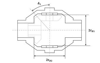
The mounting distances of the planet gears tB1 can be obtained from the differential housing by measuring the distance between the contact surfaces of two opposite planet gears using a caliper. If a friction washer is present between the planet gear’s back face and the differential nest, its thickness should be included when estimating the mounting distance, as illustrated in Figure 2.
Figure 2—Differential housing and mounting distances.
RZ Projection
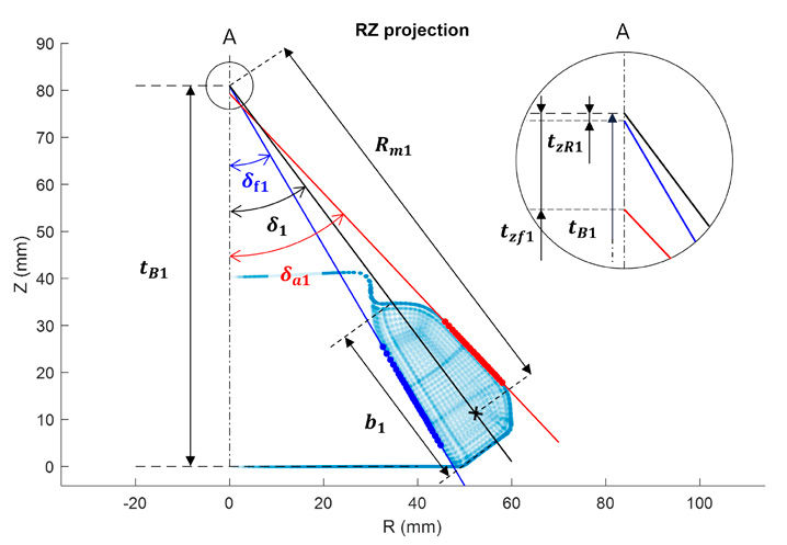
Once the basic geometry has been established, the Cartesian coordinates obtained from 3D scanning are projected onto the RZ plane. The objective of this step is to determine the face angle (δa1) and root angle (δf1) along with the face apex beyond crossing point (tzF1) and root apex beyond crossing point (tzR1) of the scanned planet gear.
For that purpose, the highest and lowest points along the gear flank—defining the face and root cones, respectively—were identified and isolated. These sets of points should form straight, continuous lines. Any points associated with root reinforcement shapes, blank outer radius, or chamfers were visually identified and removed from their respective sets. In Figure 3, root points are highlighted in blue, while face points are marked in red. A linear equation was fitted through both sets of points. For the face points, an equation in the form
(2)
was obtained. From this equation, the face angle (δa1) and face apex beyond crossing point (tzF1) can be determined using Equations 3 and 4:
(3)
(4)
[advertisement]
A negative value indicates that tzF1B1, as illustrated in Figure 3. A similar process is applied to the root points to estimate the root angle (δf1) and root apex beyond crossing point (tzR1).
Figure 3—RZ projection of planet gear points.
At this stage, the pitch angle δ1 previously defined can also be plotted on the RZ graph, given that the pitch line intersects the crossing point of RZ coordinates (0, tB1). The pinion face width (b1) was estimated as the absolute distance between the first and last point of the projected profile that intersects the pitch line.
Finally, a cone distance (Rm1) was arbitrarily defined by selecting a point along the pitch line and within the limits of the previously defined face width. This reference point will be used in the next steps to establish a transverse section of the gear. Within this section, the meshing of a straight bevel gear is considered equivalent to the meshing of a cylindrical spur gear with virtual geometric parameters. This transverse section will be used to estimate the tooth thickness, pressure angle and tool tip radius.
Transverse Section and Tooth Thickness
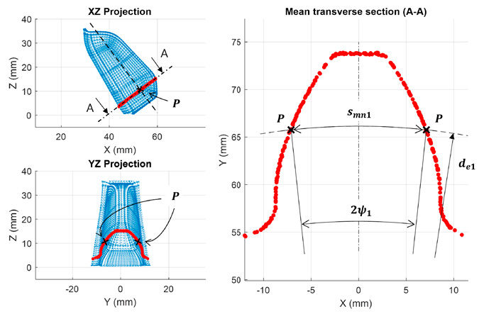
From the 3D-scanned dataset, a single tooth was isolated. A plane perpendicular to the pitch line, passing through the cone distance Rm1 was defined and designated as plane A-A in XZ and YZ projections, as shown in Figure 4 (left). The points whose distance from the plane was less than a predefined limit were identified and projected onto the latter. Simultaneously, the pitch points (P) on the left and right flanks were identified as the intersection of the transverse section points with the pitch line, illustrated with a dotted line in Figure 4 (top left). These points were then shifted in the x direction to ensure that both pitch points were equidistant from the y-axis. It can be noted that the distribution of the transverse section points closely resembles that of a cylindrical spur gear with an involute profile, exhibiting the following characteristics:
(5)
(6)
(7)
Where:
met is the transverse module
z’1 is the virtual number of teeth of the pinion
de1 is the pitch diameter of the virtual cylindrical gear
Figure 4—Transverse section and pitch point alignment.
Since this pitch diameter should intersect the two previously identified pitch points, the transverse section points were shifted in the y direction so that these points align with de1. From this, the tooth thickness half-angle (ψ1) was calculated based on the adjusted pitch point coordinates. Finally, the mean normal circular tooth thickness (smn1) was determined using:
(8)
Transverse Section and Pressure Angle
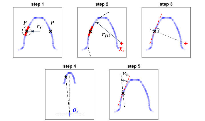
The normal pressure angle (an) of the virtual cylindrical involute gear is defined as the angle formed between a radial line of the pitch circle and the tangent line to the profile at the pitch point (Ref. 2). It can be estimated from the transverse section by following the steps illustrated in Figure 5 and described below.
Figure 5—Estimation of normal pressure angle.
Step 1: A circle centered at the previously identified pitch point (P) on one of the flanks was defined, with a search radius (rs). The points of the transverse section located within this circle were identified.
Step 2: A circle was fitted through the identified set of points to estimate the local profile radius of curvature at the pitch point. The coordinates of the center of this fitted circle, denoted as XC, were retrieved.
Step 3: A line passing through the pitch point and the fitted circle center XC was drawn, establishing the normal to the gear surface. The perpendicular to this normal, also passing through the pitch point, provides the tangent line to the profile at the pitch point.
Step 4: A radial line of the pitch circle was defined as passing through the center of the gear OC (0,0) and the pitch point.
Step 5: The normal pressure angle (αn) was estimated by calculating the angle between the tangent line (from Step 3) and the radial line (from Step 4).
It should be noted that these results may vary depending on the initial choice made for the search radius (rs). In this study, consistent and repeatable results were obtained with rs ranging from 15–25 percent of the tooth height.
Profile Shift, Addendum and Dedendum Calculation
Once the mean normal circular tooth thickness (smn1) and normal pressure angle (an) have been determined, the profile shift coefficient (xhm1) can be obtained using the following equation:
(9)
The addendum coefficient (hae1) and dedendum coefficient (hfe1) of the straight bevel planet gear at the cone distance Rm1 be determined using the face angle (δa1), root angle (δf1), face apex beyond crossing point (tzF1) and root apex beyond crossing point (tzR1) as defined in the previous section “RZ Projection”:
(10)
(11)
Where
dfe1 is the root diameter of the planet gear
dae1 is the tip diameter of the planet gear
These diameters are derived from the equivalent spur gear tip diameter (d’a1) and root diameter (d’f1) as follows:
(12)
(13)
The equivalent spur gear diameters are given by:
(14)
(15)
(16)
Where:
h’a1 is the addendum coefficient of the equivalent spur gear
h’f1 is the dedendum coefficient of the equivalent spur gear
These coefficients can be expressed in terms of profile shift coefficient (xhm1):
(17)
(18)
By substituting Equations 17 and 18 back into Equations 10 and 11, the values of hae1 and hfe1 can be isolated and calculated.
Transverse Section and Tool Tip Radius
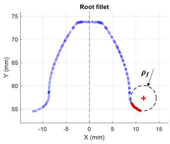
The edge radius of the hobbing tool (ra0) has been shown to be proportional to the minimum radius of curvature (ρf) in the generated root fillet (Ref. 3). This minimum radius occurs at the beginning of the trochoid, at a point where the profile is tangent to the root diameter. At this point, the relationship between these parameters is expressed as follows:
(19)
Since the pitch diameter (de1) and dedendum coefficient of equivalent spur gear (h’f1) were determined in the section “Profile Shift, Addendum and Dedendum Calculation,” the only unknown in this equation required to determine ra0 is the radius of curvature (ρf). To determine the latest, the transverse section previously established was analyzed. The points of the root fillet close to the root diameter were isolated (highlighted in red in Figure 6). A circle was then fitted through these points, allowing for an estimation of ρf as illustrated in Figure 6.
Figure 6—Estimation of the radius of curvature (ρf) in the generated root fillet.
The edge radius of the hobbing tool (ra0) was isolated from Equation 19. To reduce the uncertainty of the proposed method, this operation was repeated for the left root fillet. The mean of both obtained values was considered as the final value for ra0.
Numerical Data and Overall Check
Table 1 below presents the measured results obtained from the planet gear analyzed in this study, following the methodology described in previous sections. For confidentiality reasons, only the pinion data are provided in this article. However, the analysis was thoroughly conducted on both the sun and planet gears.
Description
Symbol
Unit
Value
Number of teeth (pinion)
z1
-
12
Number of teeth (gear)
z2
-
16
Mounting distance
tB1
mm
81
Cone distance
Rm1
mm
88
Face width
b1
mm
27.8
face angle
da1
°
43.34
root angle
df1
°
30.46
face apex beyond crossing point
tzF1
mm
-2.08
root apex beyond crossing point
tzR1
mm
-0.14
Tooth thickness half angle
}1
°
6.21
Normal pressure angle
an
°
27.0
Minimum radius of curvature at root fillet
tf
mm
2.48
Table 1—Measured numerical data from physical parts using the proposed methodology.
Using the measured data from Table 1, the remaining geometrical parameters were computed using the equations provided in this study. Results are provided in Table 2.
Description
Symbol
Unit
Value
Pitch angle
d1
°
36.87
Equivalent pitch diameter
de1
mm
105.6
Mean normal circular tooth thickness
smn1
mm
14.32
Transverse module
met
mm
8.8
Virtual number of teeth of equivalent spur gear
z’1
-
15
Profile shift coefficient
xhm1
-
0.055
Addendum coefficient
hae1
-
8.543
Dedendum coefficient
hfe1
-
9.958
Edge radius of the tool
ra0
mm
1.232
Table 2—Numerical data calculated using provided equations.
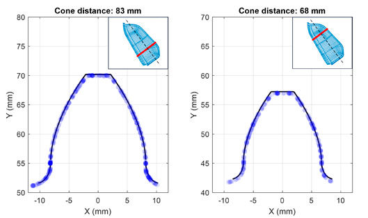
A simple approach to validate the identified macrogeometry is to compute, in a transverse section defined by its cone distance Rm all the geometrical parameters of the equivalent cylindrical spur gear. From there, using equations for involute profile and trochoidal root, one can compare the theoretical tooth shape with the physical points of the scanned dataset at the defined section. This comparison is illustrated in Figure 7, where the theoretical tooth shape is represented as a dark continuous line, while the physical scanned points appear as blue scattered points. The comparison is performed at two different cone distances—close to the toe and heel of the planet gear—both different from the one at which the analysis was conducted.
Figure 7—Theoretical tooth shape vs. transverse section points.
At this stage, the complete macrogeometry of the differential has been identified. These data are sufficient to establish a complete gear datasheet and run basic strength calculations, including surface durability and tooth root strength as per ISO 10300 (Ref. 4). However, an additional step could be achieved by overcoming the challenge of accurately reconstructing the microgeometry of both gears.
Topographic Measurement and Contact Ease-Off
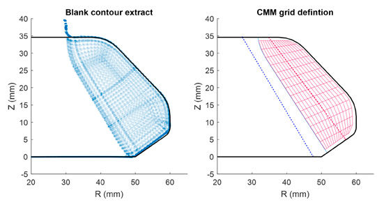
In this final section, the gear blank shape was extracted from an RZ projection, capturing parameters such as the back cone angle, root reinforcement and tip radii, as shown in Figure 8 (left). Using this data alongside the previously determined macrogeometry, an initial approximation of the tooth surface microgeometry was established.
To refine this approximation, a 15 x 15 measurement grid was created, precisely following the gear contour, as depicted in Figure 8 (right). Each grid point contains x,y,z coordinates and the normal to the tooth surface.
Figure 8—Blank contour extract, CMM grid and contact ease-off.
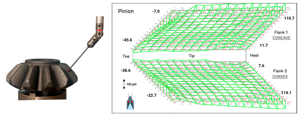
The planet gear analyzed in this study was then placed on a coordinate measuring machine (CMM) to measure the exact surface deviation at each point in the normal direction, as presented in Figure 9 (left). The CMM inspection report (Figure 9, right) revealed reasonable amplitudes of the surface deviation, confirming the validity of the initial microgeometry assumption. The final microgeometry was determined by combining the initial estimation with the measured deviations.
Figure 9—CMM evaluation and inspection report.
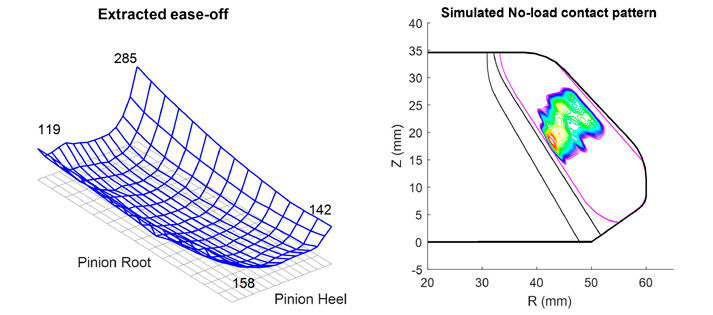
Applying the same method to the side gear enables the determination of the geometric ease-off. The extracted ease-off topography is represented on the pinion in Figure 10 (left) as the initial gap (in µm) between mating gears. From this, standard finite element (FE)-based bevel gear calculation can be performed, enabling the accurate evaluation of durability under load, contact patterns, transmission errors and overall performance. An example is provided in Figure 10 (right), illustrating the simulated no-load contact pattern on the planet gear.
Figure 10—Extracted ease-off (gap in μm) and simulated no-load contact pattern.
Conclusion
This study presented a structured methodology for reverse-engineering the macro and microgeometry of a straight bevel gear, relying on 3D scanning, mathematical modelling and topographic measurement. Through a step-by-step approach, key geometrical parameters—including tooth thickness, pressure angle, profile shift and tool tip radius—were identified and validated against physical measurements. The final step relied on CMM for topographic evaluation to identify the microgeometry and assess contact ease-off, enabling further numerical simulations for performance evaluation. The extracted data can serve as a foundation for durability assessments and design optimization, contributing to the accurate evaluation and enhancement of gear performance.
References
International Organization for Standardization (ISO). (1998). ISO 1122-1: Vocabulary of gear terms—Part 1: Definitions related to geometry.
American Gear Manufacturers Association (AGMA). (2005). Gear nomenclature: Definition of terms with symbols (ANSI/AGMA 1012-G05). ISBN 1-55589-846-7. OCLC 65562739.
Townsend, D. P. (1992). Dudley’s Gear Handbook. McGraw-Hill, New York.
International Organization for Standardization (ISO). (2014). ISO 10300: Calculation of load capacity of bevel gears—Parts 1–3. Second edition, April 1, 2014.
A version of this paper was first presented at the 2024 Fall Technical Meeting (FTM), October 7–9, 2024, Rosemont, IL. Printed with permission of the author(s). Statements presented in this paper are those of the author(s) and may not represent the position or opinion of the American Gear Manufacturers Association.