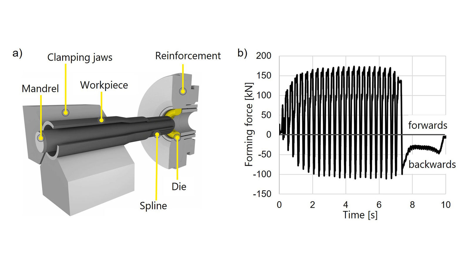
Figure 1—Axial forming process, including a) the process setup and b) the specific force curve.
The automotive industry and its suppliers are undergoing profound structural change. Electrification, volatile markets and geopolitical instability, along with increasingly intense global competition, are creating high costs and innovation pressures across the entire value chain. These developments not only affect the general drivetrain components but also rotor shafts for electric motors, which combine high functional density with demanding manufacturing and quality requirements. Recent restructuring efforts, plant closures and bankruptcies have highlighted the need to critically reassess existing manufacturing concepts, especially for components such as rotor shafts with integrated functional elements. For automotive suppliers, technological capability and cost efficiency are no longer the only priorities; process robustness and investment security are increasingly moving into focus. New manufacturing solutions must not only be technically convincing, but also enable a substantial reduction in manufacturing costs, energy consumption, the associated CO2 emissions and process complexity (Refs. 1,2).
At the same time, the requirements for drivetrain components are undergoing fundamental change. Electrified drives operate at high rotational speeds in compact designs and set higher standards for noise performance, efficiency and power density. Helical gears play a key role in meeting these demands, as they enable improved operating characteristics and more uniform load distribution. However, their industrial production has so far been carried out primarily through machining processes, which involve material removal, multistage process chains and correspondingly high energy consumption.
Based on rising energy prices and regulatory requirements to reduce CO₂ emissions, the focus is increasing on how to make the production of highly loaded gear geometries such as those used on rotor shafts more cost-effective and resource-efficient.
Axial forming is an incremental cold forming process first patented by the Felss Group in 1997 and enables the precise production of rotationally symmetric components with integrated functional geometries. While the process is already established for spline connections, transferring axial forming to the helical gear profiles frequently used on rotor shafts introduces additional technological and mechanical challenges. Through targeted process development, supported by structural and forming simulations of the machine behavior and tool loading, a new machine generation has been developed. This machine generation provides the required kinematic capabilities and structural rigidity to form helical gears directly on rotor shafts in a dimensionally accurate and reproducible manner and, at the same time, offers a more energy-efficient and CO₂-friendly alternative to conventional machining.
Preliminary Work on the Axial Forming of Helical Gears
Axial forming is a cold forming process in which a tube or bar is reduced in cross section or formed into a specific profile. Most applications involve the production of internal and external splines. To produce external splines, the forming tool, a die with the exact negative contour of the desired gear, is guided axially over the workpiece, thereby precisely reproducing the tool contour (Figure 1a). A major advantage of this process is the simultaneous forming of all teeth using a single-piece tool, which results in excellent total pitch deviation accuracy of the produced gear.
A key feature of axial forming is modulation, where the specific force profile is shown in Figure 1b. In this approach, the forming process does not occur in a single forward stroke across the entire forming zone, but rather through a series of small, incremental forward and backward strokes. The highly loaded forming zone is exposed by short backward strokes performed between the forward strokes, allowing for relubrication. The continuous renewal of the lubricant film ensures optimal friction conditions, resulting in a significant reduction in forming forces. This is particularly beneficial for spline forming on thin-walled components without bulging or buckling, while also increasing tool life and enabling the use of simple lubricating oils. Compared to conventional extrusion processes, incremental axial forming is especially suitable for producing functional elements such as splines. Due to the locally confined forming zone and reduced process forces, components can be formed without negatively affecting adjacent areas of the component. In this process, the material is not removed but is targeted for displacement, which largely preserves the material’s fiber orientation and redirects it along the profile contour. Combined with a more uniform stress distribution within the component, this leads to improved mechanical properties, particularly with regard to fatigue strength and load-bearing capacity. At the same time, the lower forming forces enable more precise compensation of elastic deformations, resulting in high dimensional and profile accuracy.
While axial forming, with its process‑specific advantages for producing splines, is already well established both technologically and industrially, the manufacture of axially formed helical gears presents entirely new challenges in terms of process kinematics, machine design, drive control and tool design. The results of numerical and experimental investigations, including a new generation of machines equipped with an additional electric rotary drive for the axial forming of helical gears, are outlined below.
Requirements for Helical Gearing on the Machine and Tool
The production of splines and helical gears using axial forming requires forming presses that meet the highest standards of precision and rigidity. Only in this way can dynamic loads be reliably absorbed and the required manufacturing accuracy of the gears be achieved with process stability. This applies in particular to the precise alignment of all components involved in the load path, especially tools, mandrels, clamping devices and workpieces, which must exhibit only minimal deviations in coaxiality relative to one another. To ensure that this accuracy is maintained across the entire gear length, the axis guides must provide excellent overall runout as well as high repeatability and positioning accuracy. This prevents geometric errors such as runout or wobble and protects the tools from unacceptable transverse loads caused by tilting or off-center loading.
These basic requirements apply equally to presses used for manufacturing helical gears. However, the additional rotational kinematics raise further technical requirements. Since helical gears are produced by the superposition of axial and rotational tool movements, which are provided by separate drives, highly precise control of these movements is essential. The electric rotary axis and the hydraulic stroke axis must operate in precise synchronization both during stationary operation and during acceleration phases, as well as during the cyclic reversal of the modulation.
Furthermore, the rotational axis must be designed to be free of play and torsionally rigid so that the required pivoting angles can be achieved with high precision even under heavy loads. Only in this way can the helix angle and the resulting gear tolerances, such as total helix deviation, be maintained. Beyond the design of the drives and guides, the entire press frame must also provide the necessary rigidity to safely absorb the torques introduced by the rotary drive without significant elastic torsion or elongation. If these conditions are met, the workpiece itself becomes the most compliant element in the overall system consisting of the press frame, tools and clamping device. In conventional axial forming of splines, this compliance has only a minor effect, as the resulting component deviations occur primarily in the axial direction and can be directly compensated by tolerances or by a simple correction of the final position. In helical gear forming, however, the situation is significantly more complex, since elastic strain and torsion components do not remain constant throughout the process and can influence the helix angle. These factors must therefore be considered and compensated for already during the forming operation. As the tool moves toward the clamping device, the length of the component, over which the torque from the helical gear forming acts, decreases. Consequently, the effective angular error resulting from the torsional elasticity of the workpiece is reduced over the course of the process and must be accounted for in the machine control system.
In addition to the elastic effects, the risk of undesired plastic deformation of the workpiece must also be considered. While conventional axial forming transmits only compressive forces through the workpiece into the clamping device, the additional rotational movement in helical forming generates torsional stresses that must be safely absorbed and withstood by the component. As the outer diameter increases, the polar moment of inertia of the workpiece and thus its torsional stiffness also increases, thereby reducing the risk of unwanted stress-induced deformation.
The tools, as well as the tool assembly consisting of the die and the reinforcement, are subject to more stringent requirements necessary for the axial forming of helical gears. The reinforcement assembly performs several mechanically critical functions in this process. The preload generated in the die ensures that the high internal pressures occurring during the forming process are absorbed. At the same time, the radial stiffening of the system reduces elastic die deformation, thereby improving the dimensional accuracy of the resulting gear.
Beyond these functions, the press fit also serves to mechanically fix the die. Although the axial forming forces are transmitted through a positive fit, the die is retracted during the backward stroke and prevented from slipping or rotating during helical gear forming by the frictional fit in the reinforcement. This requires a specifically engineered press‑fit design. The frictional stresses must be high enough to reliably transmit the required torque, while the permissible radial press‑fit limits must not be exceeded, as excessive reinforcement would lead to unacceptable stress conditions and material damage.
The helix angle in helical gears generates additional lateral loads on the tooth profile of the die. These loads are the primary cause of failure in the form of tooth breakage. The shear stress occurring in the tooth root must therefore remain within permissible limits. Likewise, inaccuracies in tool movement must be avoided, as even minor deviations lead to increased transverse and bending moments on the teeth and significantly exacerbate the stress situation.
Due to these constraints, the design of the gear profile requires careful selection of the manufacturing process. Each available manufacturing technology produces specific geometric characteristics, such as edge radii, surface roughness or manufacturing deviations, that directly influence tool loading and the achievable component quality. Experimental investigations and numerical forming simulations were used to determine the optimal combination of manufacturing process and tool loading.
Influence of the Die Geometry
[advertisement]
While the die contour for helical gears can be freely optimized in numerical simulations, many of these geometries cannot be manufactured in practice or only with considerable effort. For this reason, two practical and industry-established manufacturing routes, wire electrical discharge machining (EDM) and sinker EDM, were evaluated with respect to their geometric flexibility, cost efficiency, and their influence on the forming process.
Wire EDM represents the more economically attractive option. It offers short manufacturing times, high repeatability and low tool costs. Although the constraints imposed by the continuous wire path limit the achievable geometric freedom, particularly for helical contours or calibration sections, a wire-EDMed die can still be designed to serve as a robust and process-reliable tool for a wide range of gear geometries.
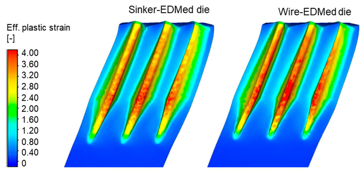
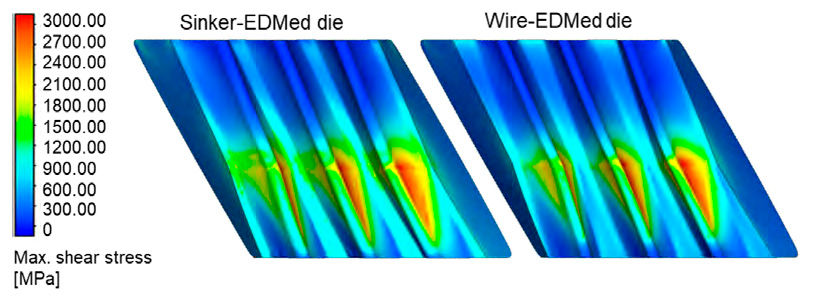
Figure 2—Comparison of the simulated effective plastic strain on the toothed component produced using a sinker-EDMed and a wire-EDMed die.Figure 3—Comparison of the simulated maximum shear stress in the sinker-EDMed and wire-EDMed dies during the forming process.
In comparison, sinker EDM provides significantly greater geometric flexibility. It enables the fabrication of spatially curved contours, defined calibration sections, and complex helical shapes, which in principle allows for a more accurate reproduction of the target gear geometry. This increased design freedom, however, is accompanied by higher manufacturing costs and a more demanding electrode production process, which can impose economic limitations, particularly in environments with high product variability or small batch sizes.
To assess the actual influence of both manufacturing approaches on the forming process, die variants produced by wire EDM and sinker EDM were analyzed using numerical forming simulations. The simulation results shown in Figure 2 illustrate the investigated gear with a pitch diameter of 55.3 mm, 26 teeth, a module of 1.8, and a helix angle of 22.5 degrees. By utilizing the cyclic symmetry capabilities of the Simufact software, a helical segment of 41.5 degrees, corresponding to three teeth, could be simulated, enabling a high spatial resolution of the material flow while significantly reducing computational effort.
The simulation results indicate that the sinker-EDMed die generates a highly uniform material flow due to its contour-conforming helical geometry. The frictional conditions on both tooth flanks remain nearly identical, which promotes a slightly more complete formation of the tooth tip and a more symmetrical shaping of the flanks. This behavior results primarily from the continuous geometric guidance provided by the true helix contour.
Due to geometric constraints imposed by the wire path, the wire-EDMed die exhibits a slight deviation from the ideal helical profile. This deviation must be compensated during the forming process through the material flow, which results in locally increased effective plastic strain. This effect is also reflected in the required torque, which is approximately 3.5 times higher than that of the sinker-EDMed variant. This does not constitute a fundamental disadvantage; rather, it indicates that the wire-EDMed die relies more strongly on process force regulation to reproducibly achieve the target gear geometry. Moreover, the minor differences in tooth tip filling can be fully compensated by adjusting the initial outside diameter of the preform, a parameter that is tailored for each gear anyway to account for material and batch-dependent deviations between simulation and actual forming behavior.
The approximately 20 percent higher axial force observed for the sinker-EDMed die is attributable to the enlarged contact area resulting from the more pronounced tooth geometry and the integrated calibration section. While this increased contact area has a beneficial effect on component quality by further reducing the total helix deviation, the longer calibration section requires a longer retraction stroke during modulation, which can accelerate tool wear. Conversely, if the retraction stroke is not adjusted to match the length of the calibration section, insufficient relubrication may occur, which can adversely affect the frictional conditions during the process.
The maximum shear stresses shown in Figure 3 reveal only minor differences between the two tooling concepts. This confirms that the wire-EDMed die exhibits a very favorable stress distribution despite its simplified contour and the higher torque required during forming. Its smaller effective contact area reduces the transverse loading on the teeth, making the tool less sensitive to minor positional deviations. In addition, the adapted entry and exit geometry provides design flexibility that enables targeted process adjustments, for instance, through modification of the helix angle. In contrast, the sinker-EDMed die, due to its closer approximation of the ideal target contour, exhibits a larger contact and effective area, which increases the transverse loading on the teeth, particularly when small deviations from the ideal helix angle occur.
Overall, the simulation study demonstrates that the wire-EDMed die is the preferred solution for many applications due to its lower force requirements, its higher robustness with respect to positional deviations, and its more cost-effective manufacturability. The sinker-EDMed version offers advantages primarily in cases where the highest demands on lead accuracy are required and where a potentially shorter tool life is acceptable in favor of maximum profile fidelity.
From Prototype to a New Generation of Machines for Helical Gears
The prototype used for the evaluation was based on a conventional axial forming press equipped with a servo-electric rotary drive, providing the kinematic capability required for helical gear forming. The experimental trials showed that helical gears could indeed be produced, although the resulting component quality did not yet meet the required specifications. The observed profile slope deviation and total helix deviation led to the early conclusion that the torsional stiffness of the machine frame was insufficient to withstand the complex loading conditions of helical gear forming. This made a detailed structural analysis necessary to quantify the cause-and-effect relationships between machine stiffness and the resulting gear geometry.
Based on these findings, structural FEM simulations were conducted to systematically investigate the torsional behavior of the system. The simulated loads were intentionally increased conservatively compared to the actual process parameters in order to account for both safety margins and potential scaling possibilities. All FEM simulations were conducted using identical boundary conditions, including an applied torque of 9,000 Nm. The resulting torsion angle was evaluated at two critical positions: the forming axis and the clamping device. The relative deformation between these points is crucial for process accuracy, as this is where the direct tool-workpiece interaction occurs. Even minor elastic torsional deflections can lead to measurable deviations in the resulting gear geometry.
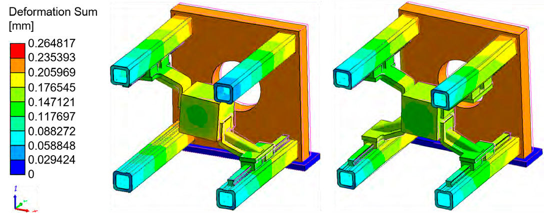
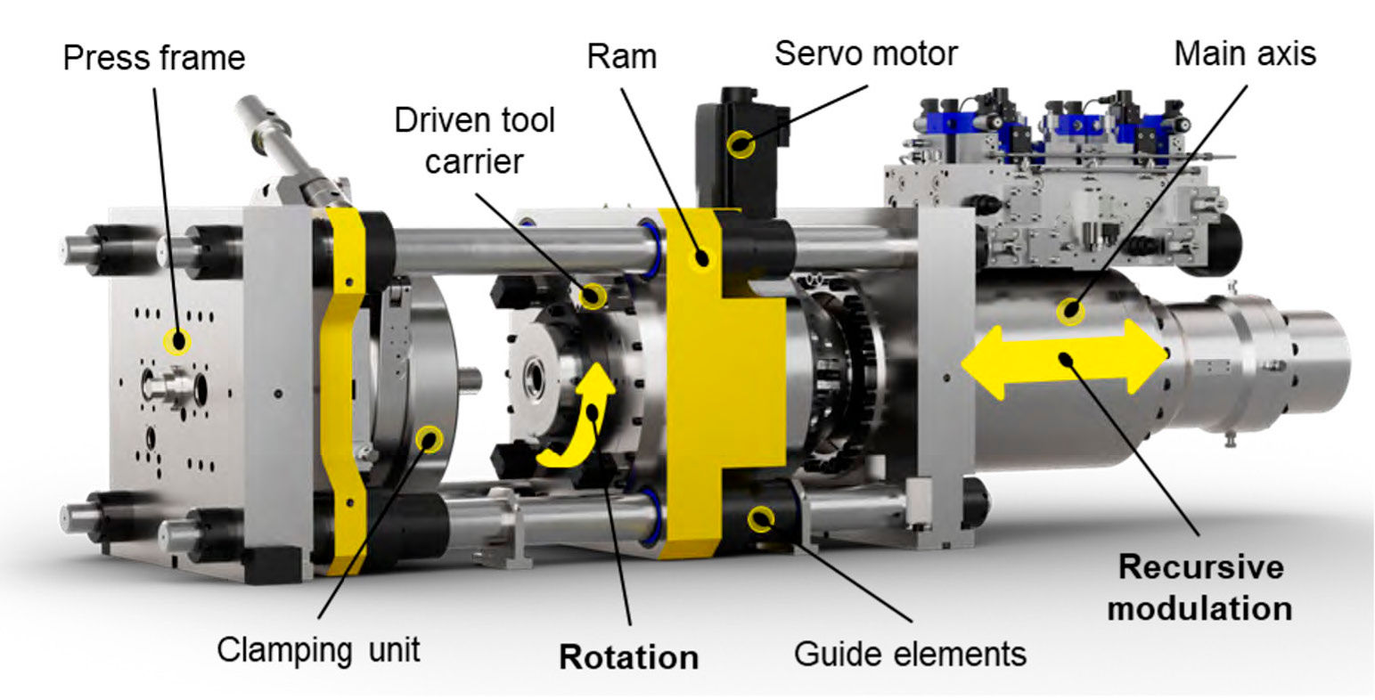
Figure 4—Comparison of the simulated deformation of the press frame under load using different guide systems (Ref. 3).Figure 5—Newly developed generation of axial forming machines for the production of helical gears (Ref. 4).
The results of these analyses enabled a targeted evaluation of alternative guidance concepts. The original dual-arm configuration of the prototype shown in Figure 4a exhibited significant torsional deformation of the tool holder. The version with additional guide arms, shown in Figure 4b, was substantially stiffer. Simulation and experimental results both showed that it reduced the torsional deflection by about 41 percent. This was directly reflected in improved gear tolerances and confirmed the effectiveness of the modified guidance concept.
For the development of a new generation of machines specifically designed for helical gears, the objective was to reduce torsional deflection by at least 50 percent compared to the first prototype system, in order to significantly expand the process limits. This target was not only achieved but clearly exceeded. The new concept incorporates four highly rigid guide columns with internal tie rods, enabling a nearly closed and flexurally rigid load path between the press plates. The comparison of torsional deformations for the evaluated guidance and machine concepts, as shown in Table 1, indicates that the new machine generation reduces torsional deflection by 78.6 percent compared to the prototype configuration, which corresponds to nearly five times the torsional stiffness. This improvement provides the necessary precision and process reliability for helical gear forming for the first time.
The helical gear machine (Figure 5) is designed to substantially expand the process window of the previous axial forming machine. Its press plates, tie rods and column guides form a highly rigid assembly that keeps tool movement virtually free of tilt, and a tandem cylinder, with its larger piston area, provides higher axial forces. The mandrel axis inside the tandem cylinder supports the inner diameter of tubular workpieces or parts with internal bores and keeps thin-walled components from buckling.
Evaluation of torsional stiffness at 9000 Nm
Machine type
Total torsion
Reduction in torsion
Aximus H02 dual guide
9.753 x 10⁻⁴ rad 0.0559°
Reference
Aximus H02 four guide
5.785 x 10⁻⁴ rad 0.0331°
40.7 %
New machine generation round guide
2.0866 x 10⁻⁴ rad 0.0120°
78.6 %
Table 1—Comparison of simulated elastic torsional deformation angles of the guide systems under load.
The central functional element of the new machine is the cylinder-driven ram, which is designed to withstand axial forces of up to 1,000 kN and incorporates a bearing system that ensures play-free rotation of the tool holder under load. Torque of up to 10 kNm is supplied by a play-free system consisting of a servo motor and gear assembly, enabling highly dynamic and precise rotational movement of the tool. A switchable clutch also allows the system to operate in a freely rotating mode, permitting the tool to be withdrawn from the interlocking mechanism with virtually no load once the forming process is complete. This protects both the tool and the component.
“For automotive suppliers, technological capability and cost efficiency are no longer the only priorities; process robustness and investment security are increasingly moving into focus.”
Experimental Trials
The experimental validation of the new machine generation was carried out using a sequential testing strategy. First, all basic system functions were examined under no-load conditions to characterize the dynamic behavior of the axes and drive structures. This included modulation tests to adjust axis synchronism and evaluate the resulting positional and guiding accuracy, as well as metrological measurement of the reversal clearance in the rotary drive. In this way, it was verified that the design-specified minimum clearance is maintained and can be fully compensated by the control system.
In the next step, a characteristic torque curve was determined for the rotary drive. This curve serves to prevent overload conditions and to enable precise process monitoring during the forming operation. The map was generated using a load cell positioned on a defined lever arm. By starting the system in a controlled way with limited force, the measured tangential force could be directly converted into an equivalent drive torque. In parallel, the elastic torsional deformations of the entire system at the respective load levels were recorded so that they could be specifically compensated for during process control.
On this basis, the first helical gears with a helix angle of 16 degrees were manufactured. The results confirmed the high process capability of the new machine generation. The gear quality met the required tolerances with a substantial margin of safety. Furthermore, it was demonstrated that the total helix deviation caused by elastic effects can be fully compensated through targeted local modification of the helix angle to be formed. This adaptability also enables the deliberate creation of defined helix‑angle modifications, for example, to compensate for anticipated distortion during heat treatment.
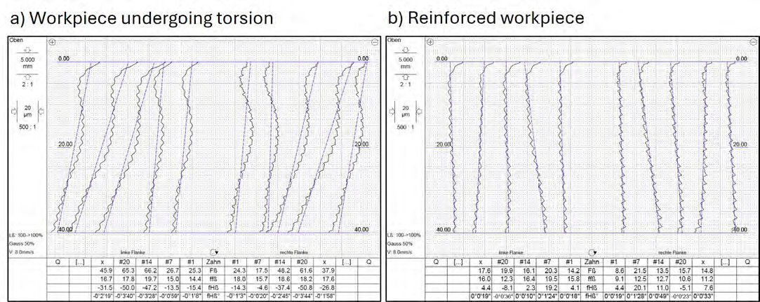
Figure 6—Comparison of tooth measurement reports for the formed gear teeth with a) lower torsional stiffness and b) higher torsional stiffness of the component.
During an extended trial phase, a helix angle of 22.5 degrees was investigated. The results showed that the combination of a higher helix angle, a reduced clamping diameter, and the resulting smaller effective cross-sectional area leads to increased local stresses in the workpiece. Consequently, for certain blank geometries, plastic torsional deformations of the shaft occurred, causing the resulting helix angle on the component to deviate from the target value defined by the machine. Although this deformation was not detectable externally, it could be clearly identified via the resulting profile deviations (see Figure 6a). By selecting a blank with higher torsional stiffness, it was subsequently possible to produce gear teeth that fully meet the specifications of the technical drawing, thereby confirming the fundamental suitability of the process for larger helix angles (Figure 6b). The results thus demonstrate that the reliable production of helical gears with high helix angles depends significantly on a suitable blank geometry, whose torsional stiffness sufficiently counteracts the resulting stresses and thereby ensures the complete reproduction of the helix angle specified for the forming process.
Summary
The development of the new generation of machines demonstrates that the key challenges in the axial forming of helical gears have been successfully overcome. Thanks to the significantly increased torsional rigidity of the press frame, the precise synchronization of the axes, and the high-performance tool mounting, a process window has been established that enables the reproducible forming of helical gears. Investigations of the die contours demonstrate that both wire-EDM and sinker-EDM dies can be used reliably in the process, and each offers specific advantages. The wire-EDM design stands out for its cost-effectiveness and robustness against positional deviations, while the sinker-EDM contour demonstrates advantages where the highest requirements for total helix deviation accuracy apply. The experimental results also demonstrate the reliable production of helical gears across various helix angles. With suitable blank geometry and adapted process control, dimensionally accurate profiles can be produced and elasticity-related deviations reliably compensated for.
In summary, the axial forming process has been confirmed as a highly effective and industrially viable method for manufacturing high-load helical gears not only for rotor shafts but also for many other components requiring integrated helical gearing. The achieved results present new possibilities for the cost-effective production of gears with high profile accuracy, reduced process costs and increased energy efficiency, thereby making an important contribution to future manufacturing technology in the automotive and powertrain sectors.
Raedt, HW.: Klimapfad Massivumformung – Wege zu CO2-freien Komponenten. ATZ – Automobiltechnische Zeitschrift 124 (2022) p. 26-31.
Wurm, T.; Busse, A.; Raedt, HW.: Initiative Massiver Leichtbau – Phase III: Werkstofflicher Leichtbau für Hybrid-Pkw und schweren Lkw. ATZ - Automobiltechnische Zeitschrift 121 (2019) p. 16-23.
Missal, N.: Umweltfreundliche Fertigung von Rotorwellen. Ein innovativer Weg zu Effizienz, Kostenreduktion und Verringerung des CO2-Fußabdruckes – 37. Jahrestreffen der Kaltmassivumformer 2024.
Missal, N.; Beihofer D.: Effizient. Intelligent. Nachhaltig. Die neue innovative Felss-Lösung für Rotorwellen – 39. Jahrestreffen der Kaltmassivumformer 2026.