Compliance Without Compromise
Klingelnberg examines e-Mobility in gear manufacturing
What will change when instead of a combustion engine an electric motor with identical nominal power will move a vehicle? At first sight not much. The higher motor speed causes a higher ratio, but the big challenge is the coast side, which did not need much attention in the past.
The root cause for changing the requirement book of an electric axle drive is the very low on-board energy content. An 80-liter diesel tank contains 784 kWh whereas a lithium ionic battery with 500 kg has 75 kWh and only 55 kWh are usable. This requires a very economical use of energy. Instead of stopping with friction-based brakes, the kinetic energy of the vehicle is used for charging the battery by running the electric motor in generator mode. The breaking power for vehicles with 2.5 tons weight is up to 250 kW, heavier vehicles will even need higher breaking power. In many cases the power for breaking is higher than the power needed for traction. Hence, load induced deflection becomes an important issue in designing the gears.
On one hand the gearbox has to transmit the traction power from zero to 15,000 rpm and even higher for moving the vehicle. On the other hand driving the motor in generator mode for breaking loads the gearbox even more than in traction mode. The only simplification in a gearbox for an electric driveline is the missing of the reverse gear. The requirement for an electric driveline has (beside the target costs) four headlines: high ratio, high torque, high efficiency, low noise emission, all this for drive and coast mode at best power density. All aspects need to comply without compromising.
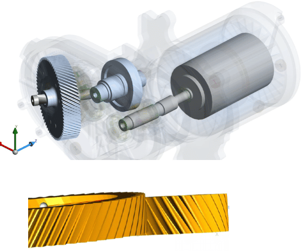
A high ratio is achievable with a two stage cylindrical gearbox or a planetary gearbox. The efficiency of the planetary gearbox is better, but manufacturing costs are higher since hard finishing the internal gear is rather time consuming. For many applications in an electric passenger car driveline the two stage cylindrical gearbox became the standard design. A shiftable gearbox will improve the efficiency of an asynchronous motor, whereas a single speed gearbox is sufficient for synchronous motors.

The high torque will cause load-induced deflections of housing, gear bodies and gear teeth. Increasing the rigidity is only acceptable without increasing the mass of the driveline. To prevent compromising power density and gearbox performance a sophisticated design of housing, gear body design and flank form modifications coping the load-induced displacements is mandatory. All these aspects have to be addressed for conventional drivelines in the same way. The challenge for electric drivelines is the amount of displacement, the consideration of the coast side and the low noise emission for all speeds and loads.
Simulation software systems for drivelines will forecast the driveline behavior closer to reality the more precise the real conditions can be described. In a first step, the static load-induced deflections need to be computed. This allows deriving the subsequent mesh-misalignments of gears. This is crucial information for introducing flank form modifications. Flank form modifications need to cope the load induced deflections and they will obviously only be effective when the mesh-misalignment of mating gears corresponds to reality.


