The following chapter is from Gear Technology Solutions (The Gleason Works, 2025) by Dr. Hermann Stadtfeld. This is the second of four excerpts provided to Gear Technology readers to preview the book’s insights into bevel gear theory, design, and manufacturing.
Why are Today’s Hypoids Perfect Crossed-Axes Gear Pairs?
In 1924, Ernest Wildhaber, a well-known gear scientist, invented hypoid gearing. Compared to spiral bevel gears, hypoid gears provide an offset that allows lowering of the body of rear-wheel-drive vehicles by 50 mm or more. This is possible because the propeller shaft between the engine/transmission and the driving axle is not positioned at the center of the drive axle but is lowered by the offset amount (Figure 1). This allows the vehicle designer to lower the floor of the vehicle and subsequently the entire body by the same amount. Lowering the center of gravity of a passenger car by 50 mm reduces the inertia responsible for sideways rolling by more than 10 percent, which provides better vehicle handling and more active safety. The lower body also reduces the CV coefficient for air resistance, providing higher gas mileage. Less than five years after the invention of hypoid gearing, all large automotive manufacturers around the world had converted their passenger cars and trucks to hypoid drive axles with a lower vehicle body.
Figure 1—Features of pinion offset.
Ernest Wildhaber emigrated from Switzerland to the USA in 1919 and was hired by The Gleason Works as a gear theoretician. Wildhaber received 279 patents, many of which changed the world of gearing. The cylindrical gear tooth profile that is today called Wildhaber-Novikov gearing was invented by Ernest Wildhaber in 1926. Mikhail Novikov, a Russian scientist with no access to Western publications, invented the same tooth profile independent of Wildhaber in 1956. The contributions of both scientists are honored today by calling this system Wildhaber-Novikov gears.
Ernest Wildhaber is the father of modern gear theory. His pioneering contributions have been invaluable for the development of today’s gear calculation and manufacturing processes.
News about Hypoid Gears?
This chapter discusses and analyzes whether hypoid gearsets, designed and manufactured today, are based on a precise theory or on approximation. As an opening statement, it can be affirmed that hypoid gearsets with a non-generated gear member and parallel depth teeth have a mathematically exact base geometry (refer to Figure 12). Also, hypoids with tapered depth teeth, which use helical motion during pinion generation, have this mathematically exact base geometry if the ring gear is non-generated.
A generalized law of gearing was interpreted by Errichello and Stadtfeld (Ref. 1) and reads: “Conjugate gears transmit uniform rotary motion from one shaft to another by means of gear teeth. The common normal to the profiles of these teeth, at all points of contact, must pass through a fixed-point P in the common connecting line that intersects the two shaft axes and is normal to the pitch element.”
The topics of this chapter are structured accordingly in:
The three fundamental laws of gearing
Perfect conjugacy
Real-world applications
Transmission design
Heat treatment, lapping and grinding
The Three Fundamental Laws of Gearing
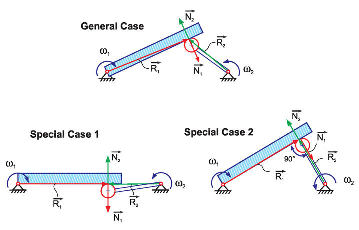
The first fundamental law of gearing ng • VR = 0, also implies |N1 × R1| = i • |N2 × R2|, where i is the constant transmission ratio. The three cases in Figure 2 visualize the problem of a non-constant ratio and are noncompliant with the first gearing law because of a ratio change from case to case. This problem led Leonard Euler to discover the involute tooth profile. A simplistic mathematical approach teaches that the effective radius vector R remains unchanged while the contacting point between two mating flanks moves from Rb2 to Rb1 as shown to the right in Figure 3 (movement along the line of action).
Figure 2—Three general cases of motion transmission with a bar and a crank.Figure 3—Line of action between base circles (left) and subsequent involute development.
The line of action in parallel axes cylindrical gearing is straight, connecting the two base circles. If the surface normal vectors N1 and N2 are within the line of action, then the vector product |Ni ×Ri| remains constant during a complete mesh cycle. The consequent application of this principle leads to the construction of an involute, as shown to the right in Figure 3.
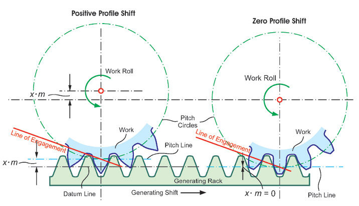
The line that forms the tooth surface elements while traveling from position “a” to “f” along the line of engagement (line of action) is always perpendicular to the line of action. This principle implies that a tool, simply with straight cutting edges as shown in Figure 4, can be used to form the complex involute profile. Figure 4 also demonstrates the principle of profile shift, while maintaining the first fundamental law of gearing.
Figure 4—Generating a rack with a straight profile forming involute profiles.
The second fundamental law of gearing, which was proposed in 2017 (Ref. 2), pln × Vm + ng = 0 (Ref. 1), is a redundant relationship to the first gearing law and it is limited to cylindrical gears with parallel axes and straight bevel gears without hypoid offset.
A third fundamental gearing law is proposed in Ref. 2 in two different notations. The first notation covers only the special case of ratio = 1:
The above notation applies only for cases with equal base pitch diameters between pinion and gear because the circular pitch and not the angular pitch has to be equal between pinion, gear, and the operating base pitch. The second notation:
is consistent with the requirement of equal circular pitch, which makes this notation more relevant. However, it does not add additional substance to the first law of gearing. As a conclusion, it can be stated that the first law of gearing is sufficient and applies without restrictions to all kinds of gearing.
Perfect Conjugacy in Straight Bevel Gearsets
Bevel gears with intersecting axes are the topic of a series of three papers published between October 2014 and January 2015 (Ref. 2). A straight bevel gearset with skew teeth was modeled, and a sample was manufactured. This publication addressed two points: the design of a gearset with a low tooth count and the solution for perfect conjugacy, which was successfully achieved. Also, Coniflex straight bevel gears used since the 1940s can achieve perfect conjugacy when the machine root angle is equal to the pitch angle of the manufactured gear (generated on the pitch line). This principle applies to any tooth count combination.
Straight bevel gears, such as Coniflex, have tapered depth teeth, where the pitch cones roll on each other, and the pitch apexes of the pinion and gear match the crossing point of the axes. In the standard case, the face and root cone apexes also match the crossing point. In such a standard Coniflex design, the base elements are also cones with cone apexes that match the crossing point of the axes. The involute development in Figure 3 can be applied to an infinite number of normal sections along the face width of a straight bevel gear, which allows an involute development like that for cylindrical gears. The conical base elements of both members can be connected with a straight line (the line of action) in each section along the face width, whereas the plurality of all lines of action forms a plane (the plane of action).
[advertisement]
This principle is shown in Figure 5. The two cones in Figure 5 are base cones of a straight bevel or a spiral bevel gearset. In the right two graphics, the view is directed such that the plane of action appears as a line that is tangential to the two cones enveloping surfaces. The left side graphic in Figure 5 shows the plane of action three-dimensionally and how it connects the two base elements.
Figure 5—Conical base elements and plane of engagement.
The plane of action cannot be extended beyond its tangential contacting line with the base elements, as shown in Figure 5. The plane of action only exists where tooth engagement is possible, and it is different than the generating gear plane (more specifically explained below).
There is, however, one difference from the true involute of cylindrical gears. The rotation of the pinion and gear does not occur in the normal plane but in the transverse plane. Because of this difference, the flank profile of straight bevel gears (and all other bevel gear types) is called Octoide. The Octoide is the analog function of an involute, and it provides bevel gears with the same advantages as an involute provides to cylindrical gears. Those advantages are constant ratio, center distance insensitivity, and ease of manufacturing.
Like cylindrical gears, bevel gears also have a trapezoidal generating profile. The straight rack of cylindrical gears becomes a ring, as shown in Figure 6. It is required to establish certain conditions to make the ring rack the generating gear for a pinion and a ring gear that will mesh perfectly together with zero transmission error and line contact identical to cylindrical gears. Those conditions are postulated in the kinematic coupling requirements:
The flank surfaces of the generating gears of the two mating bevel gears are congruent (same shape but mirror images, as given in the example of Figure 6)
The generating gears of the two mating bevel gears require identical axes of rotation (the top and bottom of the generating gear in Figure 6 form the same generating gear, which rotates in both cases around the same axis and therefore satisfies condition 2)
The surface of engagement of pinion and ring gear must be identical to the surface of engagement between pinion and generating gear, and to the one between ring gear and generating gear (without detailed knowledge of the surfaces of engagement, the global condition in Figure 6 seems to satisfy this requirement)
Figure 6—Ring-shaped generating rack with trapezoidal profile.
The generating gear principle must be understood as the ultimate vehicle to form the teeth of two mating gears. The first fundamental law of gearing is fully executed by choosing trapezoidal profiles and by applying the kinematic coupling requirements. Gears are designed and manufactured to mesh with each other. What better way to manufacture them than by way of a generating gear? The generating gear is represented by the manufacturing machine; it forms the teeth of the gear (at the bottom in Figure 6) while meshing with this gear perfectly. If the pinion is manufactured with the same generating gear but on the opposite side (at the top in Figure 6) and if the generating gear is imagined infinitely thin, then the result is a pinion that perfectly meshes with the gear having zero motion error. It is also given in such a case that line contact between the pinion and gear flank surfaces exists along the entire face width.
Coniflex Pro designed straight bevel gears are manufactured with peripheral cutters, where the tangent to the cutter tip circle is aligned with the root line of the tapered tooth, and the blade profile is aligned with the profile on one side of a generating gear tooth (Figure 6). With this process, it is required that, first, e.g., all left flanks are machined. In a second step, the cutter changes its orientation such that the blade profile aligns now with the second side of a generating gear tooth, and e.g., all right flanks are machined. This way, the generating roll, which is a rotation around the generating gear axis, is repeated for each slot twice. This kinematic condition satisfies the requirement from Figure 6 and fulfills the kinematic coupling conditions. Coniflex is the fastest straight bevel gear manufacturing process, although each slot is addressed twice to generate both flanks.
An example straight bevel gearset computer model is shown in Figure 7. The solid model in Figure 7 has been generated by using standard Gleason basic settings, based on the generating gear approach, and by applying a standard Coniflex Plus cutter head as used on Phoenix bevel gear manufacturing machines. The Coniflex straight bevel gear calculation for conjugate contact must be conducted with a dish angle of zero degrees and no root angle correction (DGammaM = 0). The dish angle is creating the length crowning, and the profile crowning is commonly generated with a DGammaM (machine root angle correction). With a dish angle of zero degrees and a DGammaM of zero degrees, flank lead lines are straight lines, and the profile is a true Octoide (involute equivalent).
Figure 7—Solid model computer graphic of a perfectly conjugate straight bevel gearset.
A contact analysis of the gearset in Figure 7 is shown in Figure 8. The top of the figure shows the Ease-Offs of the left and right flanks (called the coast and drive side in the graphic). The center of the figure shows the motion transmission errors of the pinion and gear flank pairs. The two bottom graphics are the representation of the tooth contact pattern. The contact pattern graphics are axial projections of the flank surfaces and the contact lines in the same plane where a two-dimensional part print would show the tooth area.
The contact analysis in Figure 8 confirms the full line contact in each roll position (lower graphics) as well as the zero motion error (only numerical static) in the center graphic, which makes this example a perfectly conjugate straight bevel gearset. In the lower graphic, the path of contact was calculated as a zig-zag line, which indicates an undefined contact path. This means that due to the conjugacy, every point along each contact line is a path of contact point which makes the analysis program pick random points.
Figure 8—Tooth contact analysis of the perfectly conjugate straight bevel gearset.
The Ease-Off base plane (top graphics in Figure 8) defines the conjugate state of a flank surface pair. Because the Ease-Off graph of the calculated flank pairs matches the presentation plane (base plane) precisely, that is proof that a conjugate and precisely rolling gearset was the input of this contact analysis calculation.
The above experiment, creating a conjugate straight bevel gearset, is strictly academic. Conjugacy is the basis of all gearsets manufactured in high volume on dedicated manufacturing machines. A conjugate bevel gearset cannot be used for power transmission because manufacturing tolerances and load-affected deflections, as well as material expansions and deformations under high operating temperatures, will result in edge contact and high load concentrations. The load concentrations already start with a moderate load and cause material damage and considerable noise emission. Although conjugacy is used as a reference for each design, predetermined amounts of length and profile crowning are applied. The right amount of crowning makes a gearset quiet and gives it the required load-carrying capacity. The crowning is shown in the Ease-Off graphics with the conjugate reference always being present as the Ease-Off base plane. Several Ease-Off examples of a gearset with length and profile crowning are shown in the proceedings of this chapter.
Perfect Conjugacy in Hypoid Gearsets
It begins to become more problematic for hypoid gears. Frequently, the pitch elements of crossed axes hypoid gears are drawn as cones. Even though the face cones of hypoid gears and pinions are machined conically, the pitch elements are hyperboloids.
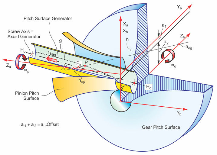
Ernest Wildhaber and Arthur Stewart described their invention of hypoid gearing in 1926 (Ref. 3). Boris Shtipelman published in 1978 the relationships and derivations required to understand hypoid gears and their hyperbolic pitch elements (Ref. 4). Figure 9 offers a graphical interpretation of the hyperbolic pitch elements and their generator. The pitch surface generator is a line that winds on the surface of a cylinder beginning at the crossing point of the axes, equal to the first contact point of the pinion and gear pitch surfaces. The pitch surface generator is developed by the connecting line between the pinion and gear pitch surfaces (nop-nog).by shifting the connecting line along the pinion and gear axes. The connecting line (nop-nog) is normal to the pitch elements. Point P is one point of the pitch surface generator. If the division of the vector products of the distances between the axes and point P and their respective axis direction equals the ratio i of the hypoid gearset, then one point of the pitch surface generator is found with:
Although the pitch elements are hyperbolic and not conical, it is possible to use conical faces for the blanks of pinion and gear. If point P in Figure 9 was chosen at the center of the face width, then line (nop-nog) can be used as a normal vector to define the face angle of a blank with straight face cones if the hypoid set was manufactured by face hobbing, which implies parallel depth teeth.
Figure 9—The correct pinion and gear pitch surfaces.
Straight face cones will merely influence the top root clearance of the gearset in the range of 30 to 60 microns. Using straight face cones will not change the form of the pitch surface, nor will it influence the base surface (and root surface). Those functional surfaces are given by kinematical relationships and must be considered when thinking about the shape of the surface of action. No plane of action can exist between two hyperbolic base elements. The correct surface of action is curved and warped, as shown in Figure 10.
Figure 10—Surface of action connecting the gear and pinion base surfaces.
The conclusion is that the first fundamental law of gearing:
is well-suited to govern the relationship of hypoid gears and can be employed to develop a conjugate relationship between two hypoid members. This will be further explained and demonstrated in the following section.
Conjugacy Between Meshing Flanks
The term conjugate is used in mathematics for two or more surfaces that contact each other along a line. Since the 1970s, the term conjugate has also been employed in gear technology literature to define the “exact” gear pair that presents a triple plurality of line contact between two gear flanks during the meshing process (Ref. 5):
The flanks contact along a line (contact line), which is only limited by the boundaries of the teeth, i.e., the working area
The line contact between the flanks exists within the entire area of engagement in every mesh position
Line contact is maintained in the entire area of engagement if the pinion and ring gear are rotated by angular increments, where: (angular pinion increment) / (angular ring gear increment) = (transmission ratio)
The Ease-Off is a three-dimensional graphic of the flank deviations from a conjugate pair. It is calculated by the transformation of a pinion flank “into” the gear coordinate system according to the first gearing law, resulting in a virtual gear flank that is conjugate to the actual pinion flank. This conjugate gear flank will then be compared to the present gear flank, where all differences in arc length are plotted point by point in ordinate direction into the Ease-Off graphic.
If both mating bevel gears have conjugate manufacturing data, then the Ease-Off graphic has no deviations in the ordinate direction. Also, if the pinion flanks and the gear flanks have spiral-angle and pressure-angle errors of equal amounts, the Ease-Off graphic will not show any deviation. Although the individual gears are considered incorrect in this case, they will roll conjugate with each other, which subsequently leads to an Ease-Off without any ordinate values. Figure 11 shows the analysis results of a typical conjugate hypoid gearset. The Ease-Off graphics have zero crowning magnitudes in the ordinate direction. The motion graph has, next to some numerical entrance and exit variation, zero motion error. The contact bearings show line contact within the entire working area. The coast side contact ends at a toe root undercut (section f).
Figure 11—Ease-offs, motion graphs, and contact lines of a real conjugate hypoid gearset.
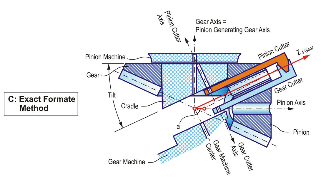
Each spiral bevel gearset with uniform tooth depth has a conjugate base design. This applies to all face-hobbed and some face-milled gearsets. Hypoid gearsets can only be conjugate with a non-generated gear that meshes with a generated pinion. For the calculation and manufacturing process, the hyperbolic pitch elements are calculated for the gear first. Then a suitable blade profile (gear cutter in Figure 12) is chosen and positioned in a face cutter head. The cutter head is positioned to create the desired spiral angle. With this procedure, a non-generated gear can be created by computer simulation, and it can be manufactured with a bevel gear cutting machine (Ref. 6).
A pinion cutter (see Figure 12) is positioned in a mathematical model or in a bevel gear cutting machine such that it represents one tooth of the non-generated gear by rotating around its axis. An additional simultaneous rotation around the pinion generating gear axis results in this pinion cutter becoming the generating gear of a conjugate pinion. If the pinion is positioned with the same offset “a” that was used to determine the pitch surfaces (Figure 9), then the cutter rotation around the pinion generating gear axis will form a pinion that is perfectly conjugate to the non-generated gear. The tooth contact analysis in Figure 11 has been obtained from such a non-generated hypoid gearset and therefore shows perfect conjugacy.
Figure 12—Generating a perfect conjugate hypoid pair.
More complicated is the generation of a conjugate bevel or hypoid gearset with tapered depth teeth (see Figure 13). If the generating gear axes have identical axes of rotation that are perpendicular to the pitch line, the rotating cutter heads and their blades will not follow the root line of a tapered depth tooth. Tilting the cutter head to follow the root line would violate the first kinematic coupling requirement for teeth that are congruent to the slots of the mating member. The following solution was developed in the 1940s (Ref. 7). If the cutting edges are adjusted in the cutting machine such that the tooth reference profile and depth are matched at midface, and if an axial motion of the cradle is introduced that guides the blades along the tapered root line while the generating roll progresses along the face width, then the requirements of congruent teeth and slots are fulfilled with the result of perfect conjugacy. However, in the case of hypoids, the gear must be non-generated, and the pinion must be generated with helical motion to achieve conjugacy.
Figure 13—Generating a conjugate tapered depth bevel gearset.
The process configuration and kinematics in Figure 13 are called duplex completing. Today, all face-milled and ground spiral bevel and hypoid gears are manufactured with the duplex completing process. The axial cradle movement in this process is called helical motion and was first introduced with mechanical bevel gear machines in the late 1940s. The helical motion of the days of mechanical machines required an additional change gearbox which actuated a cam that moved the sliding base during the generation process.
Today’s CNC-controlled Phoenix free form machines have the helical motion capability automatically through their interpolated axes movement.
Why is Conjugacy not Desirable for Real World Applications?
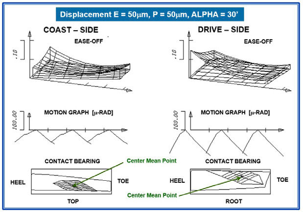
In 1926, Ernest Wildhaber (Refs. 3, 8) was the first to propose applying surface crowning on hypoid gears. Wildhaber acknowledged that the slightest deviations in the gear housing and in the building position, as well as deflections affected by load and heat, will cause edge contact with peak stress levels of a multiple of the allowable values the gearset had been designed for. The conjugate gearset used for the TCA in Figure 11 was repeated with realistic displacement values of 50 µm offset, 50 µm pinion cone, and 30’ of shaft angle change. The results in Figure 14 show warped and tilted Ease-Offs and severe edge contact on the heel and top. This edge contact will cause noisy operation, followed by pitting and tooth fracture.
Figure 14—TCA of conjugate hypoid set from Figure 11 with displacements.
The theoretically conjugate hypoid set will depart from fulfilling any of the fundamental gearing laws in case of the smallest gearbox inaccuracies or deflections. As mentioned above, already small deflections at moderate loads lead to load concentrations on the edges of conjugate flank pairs and can cause material damage and considerable noise emission. As such, the conjugate gear pair is not suitable for any task in power transmissions.
The introduction of 80 µm length crowning and 15 µm profile crowning to the conjugate hypoid design delivers the analysis results shown in Figure 15. The crowning makes the gearset insensitive to expected inaccuracies in the gear housing and load, and heat-affected deflections. Applying the same amounts of shaft displacements as those used for the TCA of the conjugate hypoid set in Figure 14 moves the mean point slightly out of the initial position (see Figure 16), but a large contact area within the tooth boundaries is still maintained.
Figure 15—TCA of the hypoid set from Figure 11 without any displacements.Figure 16—TCA of hypoid set from Figure 11 with added crowning and shaft displacement.
It was demonstrated that the hypoid gearset with length and profile crowning in Figure 15 was developed based on a conjugate design. The first and third fundamental gearing laws, mentioned in this chapter, apply to the hypoid set in Figure 15 at the mean point roll position, if the load is zero. The first and third fundamental gearing laws will apply in the area of contact as the load increases and the Hertzian contact spreads in the contact line direction as well as in the path of contact direction. This ideal condition can only be achieved with correct amounts of crowning, adjusted to the operating displacements. It is interesting to mention that a hypoid gearset with crowning will fulfill the first and third fundamental gearing law even in the case of gearbox inaccuracies.
Transmission Orientations
Hypoid gearsets are used as final drive gears in cars and trucks. Hypoid gears are not used as simple reducers, but their purpose is to redirect rotation and torque by a certain angle, commonly 90°. In case of hypoids, the second purpose of lowering the center of gravity of a vehicle body has become very important in the automotive and truck industry. The redirection of rotation and torque has to be done at the driving axle of a vehicle. The engine orientation of vehicles with a rear wheel drive is longitudinal. Because engines of cars and trucks are commonly in the front, a longitudinally oriented propeller shaft transmits the engine rotation to the rear drive axle, as shown in Figure 17. The transmission, which is located between the engine and the propeller shaft, needs to have a gear shaft orientation identical to the direction of the engine crankshaft. The hypoid gearset redirects rotation and torque and provides the final reduction at the drive axle. The advantage of this concept is the lower torque in the complex shift or automatic transmission, and the high torque only at the ring gear at the drive axle.
Figure 17—Hypoid gearset location in vehicles with rear wheel drive.
Is Lapping an Attempt to Make Hypoid Gears Conjugate?
Lapping, like grinding, is a hard finishing process. In grinding the same profile and length crowning applied in the soft cutting process is created. Grinding re-establishes the original surface function after the heat treatment. In lapping material is only removed in the tooth contact area. This not only establishes a good rolling condition, but it also makes the flank surfaces more conjugate in the area where the tooth contact patterns are located.
Lapping and grinding are hard-finishing operations. The soft-manufactured bevel and hypoid gearsets must be heat-treated, which in the most common case begins with a case carburizing of standard gear steels such as AISI 8620 or 16MnCr5. To give the low-carbon steel a surface hardness in the 60 HRc range, a layer of carbon enrichment below the surface of 0.8 to 1.5 mm depth is placed by a diffusion process. After the carburizing and quenching in oil, an additional tempering takes place. The result is a surface hardness that is commonly close to 60HRc and a core hardness in the 30HRC range. Case hardening provides an ideal transition between surface and core hardness that makes gears on the surface hard and wear resistant, and in the core ductile. This makes shock loads and certain small plastic deformations tolerable without failure of the gearset. One major side effect of the heat treatment process is the distortion of the gears that is caused by carburizing, the recrystallization of the steel, and the quenching. To make a gearset after heat treatment suitable for power transmissions, for example, in cars and trucks, a hard-finishing operation is required. The hard-finishing operating eliminates the heat treatment distortions hereby providing the flank surfaces with the correct geometry from before the heat treatment. In addition, hard finishing improves the surface finish to a low roughness and waviness, which enhances the hydrodynamic lubrication and reduces noise. Grinding and skiving are the preferred hard-finishing methods, creating a defined surface form that duplicates the original designed surfaces in the single micron range.
In case of face hobbed bevel and hypoid gearsets, grinding is not possible, because of the epicyclical flank lead function. Skiving can generate epicyclical lead functions but is not yet accepted for the high production volumes in the automotive and truck industry. This leaves only the lapping process for the hard-finishing of face-hobbed angular gearsets. However, the face hobbed surface texture and the relative sliding between the flanks of hypoid gears make lapping an ideal alternative. Lapping can remove the surface scale left from heat-treatment, and it re-matches two mating members by removing some runout and flank form distortions. Lapping can reduce the transmission error in many cases due to the fact that the major material removal is in the center region of the teeth, where the tooth contact under light load is expected. In order for the lapping to work well, more crowning than required in the hard-finished gearset is used in the gearset design for the soft cutting. Lapping removes about 30 percent of this crowning, such that the length and profile crowning are just right after the lapping. Soft cutting of parts that are lapped after heat treatment considers a stock allowance of .03 mm in the pinion and 0.01 mm in the gear. If grinding is the hard finishing process (for face-milled gearsets) then the design crowning is identical to the desired crowning after hard finishing. Between soft cutting and grinding, a uniform stock allowance of 0.10 mm to 0.15 mm is applied to the pinion and gear flanks.
Summary
Conjugacy between the members of straight bevel, spiral bevel, and hypoid gears was only the first step and goes back more than 100 years. Quickly, the early scientists and engineers found out that conjugacy only gives us an important basis, but not a solution for power transmissions. Angular gearsets under load experience deflections that move them away from their theoretical position by half a millimeter or more. Well-designed and manufactured bevel and hypoid gearsets today can live up to those requirements and still maintain a power density that is four times higher than it was 50 years ago. Transmission errors of 50 to 150 microradian that were normal in the 1970s are in today’s high-power-density gearsets only between 5 and 15 microradian. All this was achieved by converting a global length and profile crowning (Figure 18, left) first back to conjugacy (Figure 18, center) and then into a UMC-optimized selective crowning, which is limited to particular regions of the teeth, as shown in the right graphic in Figure 18. Notably, the flank center of the UMC-optimized Ease-Off is conjugate, and the transmission error is next to zero. In lapping, similar effects as in grinding are achieved by utilizing low-inertia spindles with rotational compliance and high-speed torque control (SmartLap).
Figure 18—From conventional crowning via conjugate to UMC-optimized.
The dream of conjugate angular gearsets turned out to be a false objective. Gear scientists, gear engineers, and gear manufacturers worked very successfully for many decades on finding the optimal flank forms and the optimal non-conjugate flank surface interaction. The conjugate tooth design today is considered simple compared to sophisticated higher-order surface modulation. There is still room for improvement, but this cannot be achieved by going back to antiquated conjugate designs.
References
Errichello, R. and Stadtfeld, H.J. “Conjugate Gears,” Gear Technology, March/April 2023, pp. 38–47.
Radzevich, S.P. “Design Features of Perfect Gears for Crossed-Axes Gear Pairs,” Gear Solutions, February 2019, pp. 36–43.
Wildhaber, E. and Stewart,A.J. “Design, Production and Application of the Hypoid Rear Axle Gear”, The Journal of the Society of Automotive Engineers, Vol. 18, Issue 6, June 1926, pp. 575–589.
Shtipelman, B. Design and Manufacture of Hypoid Gears, John Wiley & Sons, Inc., New York, 1978.