The following chapter is from Gear Technology Solutions (The Gleason Works, 2025) by Dr. Hermann J. Stadtfeld. This is the fourth of four excerpts provided to Gear Technology readers to preview the book’s insights into bevel gear theory, design, and manufacturing.
The Function of Couplings
Couplings are designed for a variety of duties. Hardy disks, for example, are compliant elements which connect a transmission output in a vehicle with the propeller shaft. Compliance is required to accommodate the misalignments the propeller shaft encounters when the vehicle is loaded with passengers, or if the vehicle drives on uneven pavement.
Bellows couplings are designed to transmit precise rotation between two slightly misaligned shafts. Those couplings are used to couple an encoder to an electric motor, for example. However, all couplings are, by definition, elements that do not allow any relative motion in their rotational direction. Couplings are not designed for frequent opening and closing. The two coupling halves are screwed or bolted together with the shafts they connect, and they are screwed or bolted together with each other. The coupling will stay in the connected position unless a repair or disassembly requires separating the two units that are connected by the coupling.
A good example is the Cyclocut coupling (Ref. 6), which is mostly used to connect drive shafts to the wheel hub unit. Although the drive shaft has, for example, a constant velocity joint (CV-Joint) to allow for the vertical movements of a vehicle, the CV-joint itself has one half of the coupling integrated. The wheel hub unit has the opposite coupling member integrated at the end facing the drive shaft. The coupling is the means to transmit high torque from the drive shaft to the wheel. Thus, the two coupling halves act as one solid unit after assembly. Any movement or compliance between the two coupling halves could have fatal consequences for vehicle safety.
Clutches, on the other hand, are designed for frequent connecting and disconnecting. Clutches might even accommodate some misalignment in special cases. Clutches are not bolted rigidly together like couplings.
In both cases, couplings and clutches do not perform a meshing action between their two members. In the case of couplings, this would physically not be possible because they are bolted together. In the case of clutches, the misalignment leads to unwanted friction and heating up of the units. The reason is that the tooth geometry of couplings and clutches does not have involute flank surfaces and is therefore not designed to perform any meshing action. Meshing would not even be possible, because both coupling and clutch members are facing each other without any possibility of a defined relative motion between them.
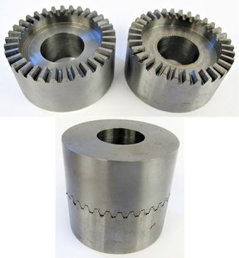
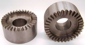
An optical example is given with the coupling in Figure 1. The two halves are fitted together in their operating position. There is no possibility of relative motion or a tooth rolling action, as the photo clearly shows.
Figure 1—Hirth coupling members, engaged.
Hirth Couplings
Hirth couplings were invented by Carl Albert Hirth in 1928 (Ref. 1). Their traditional application is in turbomachines, similar to Curvic couplings. However, most Hirth couplings are not ground, which only qualifies them for moderate speeds. There are some characteristic design elements of Hirth couplings, which are listed below:
High pressure angle, commonly 30 degrees, is used
Included pressure angle is called β (= 60 degrees)
Fully rounded root fillet from toe to heel
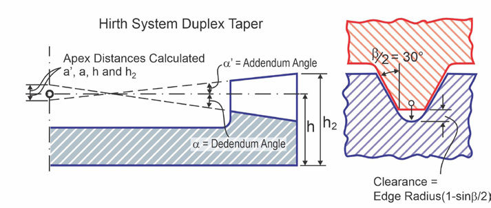
Duplex taper is used in order to achieve parallel root width
Dedendum angle is called α
Addendum angle is called α'
Both members are the same
Both members have the same strength
[advertisement]
Self-centering via opposite teeth and slots
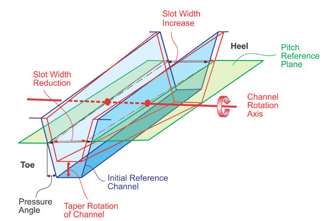
The design of a duplex taper is shown in Figure 2. The initial reference channel is defined at the center of the face width, with a parallel root width. Then it is rotated about the channel rotation axis until a slot width reduction at the toe and a slot width increase at the heel (measured in the pitch reference plane) is achieved. The slot width changes results in a slot width tapering along the face width, which is proportional to the circumference of the radius at the respective face width position (Ref. 2).
Figure 2—Cutting channel rotation to achieve a Duplex Taper.
The duplex taper makes it possible to machine the Hirth coupling slots, each in a single stroke with a disk milling cutter with cutting edge angles matching the pressure angle of the teeth. The root is fully rounded with a constant radius between toe and heel.
Topland chamfers cannot be produced with a special Flankrem design on the blades of the milling cutter because of the tapered depth slots. If topland chamfering is required, then it has to be performed in a secondary operation.
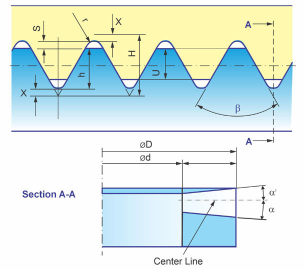
In Figure 3, there is a principal graphic of a Hirth coupling with the basic design parameters shown. The name Hirth only stands for the coupling design; there is no dedicated manufacturing process.
Figure 3—Basic design parameters of Hirth coupling.
Legend to Figure 3:
rRoot fillet radius
sRoot clearance
HTheoretical tooth depth
hActual whole depth of teeth
UProfile contact area
xAccess depth of pointed rack (2•x)
βIncluded pressure angle
DOuter diameter
dInner diameter
l Face width
αDedendum angle
α'Addendum angle
Coniflex Couplings
A new software for the design and summary calculations of Coniflex couplings has been developed recently. This new software is implemented under the name Coniflex Clutches in the GEMS bevel gear design software.
Coniflex couplings are similar to Hirth couplings. The Coniflex design parameters can be used to duplicate the typical Hirth designs. However, even when duplication of a given Hirth design is required, a remaining difference is the curved root line of Coniflex, versus the straight root line of Hirth couplings. A large cutter radius can reduce the curved root line, especially because the face width of most coupling teeth is very small, compared to bevel gears. In the case of duplicating the design parameters of a Hirth coupling, the Coniflex Clutch software can be forced, via input parameters, to match the duplex taper of a given Hirth design. In this case, the root width will also be parallel between toe and heel, which achieves the same Hirth fillet radius for a fully rounded root. The result is very fast cutting of high-quality Hirth couplings. A further advantage of the Coniflex Clutch process is the fact that grinding after heat treatment is possible.
The Formate cutting process of both members makes the Coniflex Clutch a special case of Coniflex straight bevel gears. Figure 4 shows a typical Coniflex coupling set. Unlike Hirth couplings, the root width is tapered, proportionally to the diameter change from the outside to the inside. The slot depth taper is a standard taper, which means that in addition to the slot width, the slot depth also changes proportionally with the diameter, from the heel to the toe.
Figure 4—Typical Coniflex coupling parts.
The Coniflex Clutch input screen in GEMS gives the possibility to enter a desired root angle, to duplicate, for example, the Hirth duplex taper. The input also covers a depth factor, which can be used to match the depth of a Hirth coupling. In connection with the Hirth coupling pressure angle and the fully rounded root, a perfect duplication of the Hirth geometry is possible.
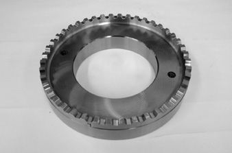
Often, Coniflex couplings are used as an alternative to Curvic couplings. Figure 5 is a photo of a Coniflex coupling member which has the typical appearance of a Curvic coupling. The Coniflex coupling is in some cases the preferred solution, especially when only cutting (no grinding) is required and when the cutting should be done on a Phoenix machine with cutters that are 9 in. or smaller in diameter. Topland chamfers like those on the part in Figure 5 are possible with the Coniflex Clutch process with blades which include Flankrem; however, the tooth depth needs to be uniform (not tapered).
Figure 5—Coniflex coupling for rotor connection.
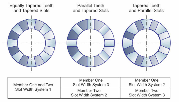
Three Slot Width Systems
In the Coniflex Clutch GEMS program, the choice is between three different slot width systems given. These systems are shown in Figure 6. Equally tapered teeth and slots are the most common system (left in Figure 6). System 2 has parallel slots and tapered teeth as shown in the center of Figure 6. The coupling member with slot width system 2 has to be paired with a member that consists of slot width system 3. Slot width system 3, as shown to the right in Figure 6, has tapered slots and parallel teeth and fits in a member having slot width system 2. Some industries require, for some reasons, designs where one member has parallel slots, and the second member has tapered slots. One frequently mentioned reason for this design is the improved self-centering, which, however, has not been scientifically proven and is solely based on practical experience.
Figure 6—Three slot width systems of Coniflex couplings.
Free Choice of Pressure Angles
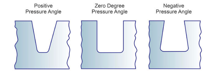
A significant advantage of Coniflex is the possibility to manufacture on standard Phoenix machines not only couplings with positive pressure angle (Figure 7, left side), but also to choose zero degree or negative pressure angles as shown in Figure 7, center and at the right side.
Figure 7—Three slot width systems of Coniflex couplings.
Due to the peripheral Coniflex Plus cutters, any customary pressure angle can be realized with the same cutter and even with the same cutting blade geometry. There is no negative machine root angle required, as in many cases of Curvic couplings with negative pressure angles. The radial tilt required for Curvic couplings with negative pressure angles requires negative machine root angles, which are limited on standard bevel-gear machines.
Free Choice of Slot Depth Taper
Due to the independent cutting of flank one and flank two in the typical Coniflex lower and upper cutting cycle, it is possible to control the slot depth taper independently from the slot width taper.
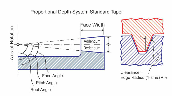
Coniflex Clutch designs use, as default, a standard taper. Standard taper means that the extension of the face line, the extension of the pitch line, and the extension of the root line all meet and intersect with the axis of rotation. This principle is shown in Figure 8. A standard taper delivers the strongest coupling regarding root bending stress of the coupling teeth. Slot width and tooth thickness are equally spaced, which means that both members have equally strong teeth.
Figure 8—Standard taper.
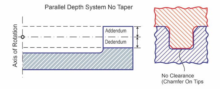
Parallel depth couplings are often chosen as fixed couplings where the members are permanently bolted together. The graphic shown in Figure 9 has a pressure angle of zero degrees and is assembled without top-root clearance and without any backlash as a transitional fit.
Figure 9—Parallel depth, no slot depth taper.
Figure 10 shows a Coniflex coupling with a duplex taper. The graphic represents the case where the Coniflex coupling duplicates precisely the geometry of a Hirth coupling. The root width is parallel, and the root fillet is rounded with a uniform radius along the face width.
Figure 10—Duplex taper with parallel root.
Flank Surfaces and Tooth Contact Analysis
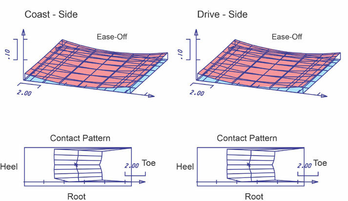
Flank surface generation and tooth contact analysis are standard features in the GEMS software system for Coniflex couplings. In Figure 11, a tooth contact analysis with Ease-Off and contact pattern is shown. The Ease-Offs have a length crowning of 20 microns and no profile crowning. Length crowning is realized as in regular Coniflex with a cutter dish angle. Because the Coniflex Clutch machining is a non-generated process, profile crowning cannot be generated kinematically as it is done in regular Coniflex. The only possibility to generate profile crowning is the application of curved blades.
Figure 11—Tooth contact analysis.
Cutting, Grinding and Closed Loop
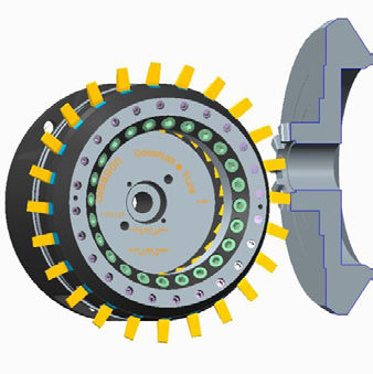
As mentioned above, both members for Coniflex couplings are cut or ground in a non-generating process. Only plunging is possible to form the flank surfaces. The lower flanks are plunged first, as shown in Figure 12. After all lower flanks (flanks 2) are cut, the cutter changes from the lower to the upper position, where it plunge cuts all flanks 1.
Figure 12—Cutting of a Coniflex coupling–CAD model.
If the slot bottom is wide, like in cases of zero degree and negative pressure angle, the fin removal function can be applied to have the blades sweep in the root width direction and clean out remaining fins or ridges. It is possible to save time for fin removal by using an increased blade point width. This has the advantage that the chip load during the plunge is not applied to a small cutting blade tip but to a wider and flat top cutting edge. Cutting with wide tips can result in a step or a fin. If sufficient top-root clearance is given, then an elegant solution is to create a gable bottom by using blades with a positive top slope angle, which is a standard in Curvic couplings (Ref. 3).
Coniflex couplings can be ground after heat treatment. Dressing of grinding wheel profiles is not possible for Coniflex gears and couplings because of the slim profile and the fact that dressing axially to the profile would change the grinding wheel diameter, which in turn would change the root geometry from part to part. The solution for Coniflex grinding was the use of permanently coated and non-dressable CBN grinding wheels.
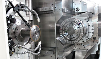
The process in Figure 13 is not a standard Coniflex coupling grinding process. Based on the large part and the large face width, the Uniflex process was applied (Ref. 4). In Uniflex, the grinding wheel moves along the face width and produces a straight root line, independent of the grinding wheel diameter.
Figure 13—Grinding of a Coniflex coupling with a CBN-grinding wheel.
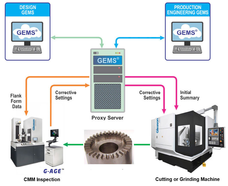
Like in regular Coniflex straight bevel gear calculations, GEMS produces a download file with flank form coordinates, normal vectors, and correction matrices for coordinate measurements with G-AGE correction output. Together with a company network, a fully automated closed-loop manufacturing can be set up.
Figure 14—Closed-loop manufacturing for Coniflex couplings.
Curvic Couplings
Curvic couplings are the gold standard for precision face couplings and clutches. The rotor wheels in jet engines and power plant turbines are all exclusively stacked together with Curvic couplings. Figure 15 shows a twin-engine airplane, where each engine uses 25 fixed Curvic couplings to connect their high- speed compressor and expansion rotors.
Figure 15—Jet engines of airplanes use Curvic couplings to stack rotors.
The main characteristic of Curvic couplings is the shape of the teeth. One member has barrel-shaped teeth while the other member has hourglass-shaped teeth. With this geometry, every single tooth, when engaged in a slot of the opposite member, contributes to self-centering between the two members. Other couplings like Coniflex or Hirth require two opposite teeth and slots to achieve a centering of a shaft in the face width direction.
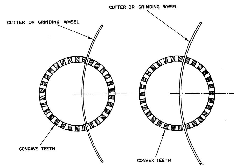
A graphic of the orientation between the grinding wheel and Curvic coupling members is shown in Figure 16. In this graphic, the outside of the grinding wheel profile forms two concave flanks of the member with hourglass-shaped teeth (left). In one revolution, all teeth are finish ground. The opposite member is ground with the inside profile of a different grinding wheel and forms two convex flanks simultaneously, which results in hourglass-shaped teeth (right graphic in Figure 16). The wheel point diameter between the left and right graphics is adjusted such that either a full-face width contact or a located contact pattern is achieved. Profile crowning is also possible by dressing a curved grinding wheel profile.
Figure 16—Grinding of two convex flanks simultaneously.
It becomes clear that a single tooth and slot centering force requires a high accuracy of the tooth surfaces. In many steam turbines, more than 50 rotors are bolted together to one unit. The radial centering must provide low radial runout, but also the axial runout has to be in the fractional micron range in order to minimize the unbalancing of a long rotor unit. There is software available which uses spacing measurement results from coordinate measuring machines to calculate an optimal timing between two rotors. If all rotors are assembled with their optimal Curvic coupling timing, then the overall runout and unbalance of a long rotor unit can be minimized to sustain the highest rotational speeds.
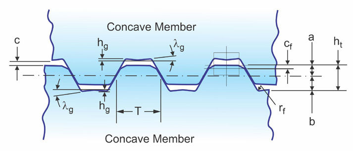
Figure 17 shows the nomenclature of Curvic coupling tooth profiles. The tooth depth of all Curvic couplings is uniform between toe and heel. The face width should be 12.5 percent or more of the outside diameter. The three types of Curvic couplings are explained in the next section.
Figure 17—Nomenclature of Curvic coupling profile.
Legend to Figure 17:
cClearance
hgGable height
λgGable angle
cfChamfer width
rfFillet radius
aAddendum
bDedendum
htwhole depth
Curvic couplings do not have a fully rounded root as the Hirth coupling. The stub tooth proportions of Curvics still allow sufficient fillet radii and a large area with a gable bottom (Ref. 2).
Flank Surfaces and Tooth Contact Analysis
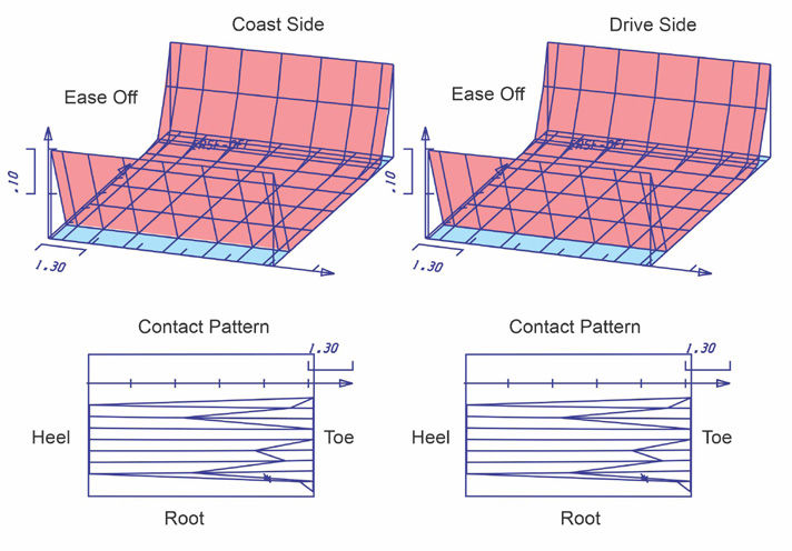
Curvic coupling design and optimization is integrated into the GEMS software system. Just recently, the software for flank surface generation was developed and added to the Curvic module in GEMS. After the design calculation, a thorough checking of the tooth contact area and even the topland chamfer or topland rounding is possible with the TCA module. The TCA module also calculates effective backlash and root clearance. Figure 18 shows the Ease-Offs of both tooth flanks of a fixed Curvic coupling with 30 degrees topland chamfers with a chamfer depth of 0.3 mm. The Ease-Offs are based on coupling member 2 (gear). The center portion in the Ease-Offs is flat, without any crowning. On top of the Ease-Offs, the reliefs created by the topland chamfers of member two are visible. At the bottom of the Ease-Offs, the reliefs from the member one topland chamfers can be observed.
Figure 18—Curvic contact analysis.
The contact patterns in Figure 18 show a full flank surface contact, which is on top and root only limited by the topland chamfers. Coordinate measurements with nominal flank coordinates and normal vectors are possible with the flank form generating module in GEMS, which generates CMM download files and also has corrective information for G-AGE corrections.
Fixed Curvic Couplings
They are precision face splines with a mostly 30-degree pressure angle, no backlash, and a very small root clearance. Root fillets are ground with a gable bottom to avoid ridges or steps. The members of a fixed Curvic coupling are bolted together to connect two or more rotating units, such as impellers of a turbine, for example, and form one operating unit. Fixed Curvic couplings are self-centering and must be manufactured by grinding with high accuracy, such as AGMA 13 (Ref. 2).
Semi-Universal Curvic Couplings
Semi-universal Curvic couplings are commonly designed with a zero-degree pressure angle and with backlash. The coupling between the two members is rather loose and includes axial play to permit up to 2 degrees of shaft misalignment. The profile on the teeth of one member is curved to keep localized contact and provide a nearly uniform motion between the two coupled shafts (Ref. 2).
Releasing Curvic Couplings (Clutches)
Releasing couplings or clutches have a helical surface to maintain proper tooth contact during engagement and disengagement of the clutch. For smaller-size clutches, this is often approximated with a special localized contact bearing. The two members of overload clutches are held in the engaged position by spring load. The spring load and the pressure angle are used to control the point of disengagement. Pressure angles of releasing clutches and overload clutches are mostly between zero and 10 degrees. Also, shift clutches are considered releasing clutches. To achieve smooth shifting and engagement, the toplands have a slope angle in the circumferential direction and are chamfered (Ref. 2).
Manufacturing of Curvic Couplings
Often the outer diameter of the rotor hub is large, for example 1,500 mm, where the Curvic coupling, which is an integral part of the rotor hub, only has a diameter of 750 mm. It requires special grinding machines, which can accommodate these large outer diameters and which can perform a roughing and finish grinding cycle. The most common Curvic coupling grinders are the Gleason No. 887 (and 887 CNC) and the Gleason No. 888 (and 888 CNC). The Curvic coupling grinders use a reverse pulse cycle for roughing, where the grinding wheel moves forward a certain pulse stroke and immediately withdraws the grinding wheel about 50 percent of the forward stroke amount. Roughing the slots stops 0.254 mm from full depth. In the finishing cycle, a different grinding wheel specification, with a finer grit and a forward pulse, is used. The wheel pulses forward and sparks out before pulsing again forward. After four to five forward pulses, a slot is finished. No. 887 and 888 grinders have a grinding wheel spindle quill that makes fast pulsing possible, avoiding moving the substantial mass of the sliding base for each pulse. Dedicated Curvic coupling grinders have a machine root angle adjustment of ±90 degrees. This freedom allows for easy loading and unloading of large rotors with a crane and also makes it possible to grind negative pressure angles.
For smaller Curvic parts, standard Phoenix cutting and grinding machines can also be used. Instead of reverse pulsing, Phoenix grinders use forward pulsing in combination with a Waguri eccentric spindle motion (Ref. 5). Grinding parts with negative pressure angles is limited with Phoenix grinders due to the limitation of negative machine root angles at -6 degrees.
Summary
Three of the most well-known face couplings have been discussed in this chapter. Gleason has only two established manufacturing processes for the manufacture of Hirth couplings, Coniflex couplings, and Curvic couplings.
Hirth couplings are designed for maximal strength with a fully rounded root, a pressure angle of 30 degrees, and a duplex taper. There is no special Hirth cutting or grinding process, which suggests that the Coniflex Clutch process is best suited regarding manufacturing speed, accuracy, surface finish, and closed-loop manufacturing possibility of Hirth couplings.
The advantage of the Coniflex coupling manufacturing method over older methods and machining center solutions is the fact that a large-size disk-shaped cutter can finish one flank in a single plunge, without the requirement of any stroke motion along the face width. This makes the Coniflex process very fast despite the single-flank cutting in a lower and upper cutting cycle. The advantage of the single-side cutting is the “unlimited” freedoms for pressure angle and tooth depth taper, for example to duplicate Hirth couplings with a fully rounded root fillet, with the same radius along the entire face width.
Curvic couplings are cut or ground with large cutter or grinding wheel diameters up to 20 in. The fixed Curvic coupling is used as a precise and stiff connection between turbine rotors. The compressor and expansion rotors in nearly every jet engine are connected with fixed Curvic couplings. Also, nearly all rotors in power plant steam turbines are bolted together with fixed Curvic couplings. There is no alternative solution to connect the high-speed rotors of gas, water, and steam turbines. The Curvic coupling cutting and grinding finishes two flanks in two different quadrants (see Figure 16) simultaneously. This arrangement only allows a cutter tilt around the vertical axis in Figure 16. Consequently, only limited corrections via machine settings are possible. Pressure angle changes can be accomplished by changing the pressure angles of the tool. Spiral angle changes are possible with a horizontal repositioning of the tool in connection with a change of the point diameter of the tool. Spiral angle cross changes can be accomplished by small amounts of vertical machine settings (which is generally zero). Semi-universal Curvic couplings have localized contact and backlash. They allow, with good lubrication, up to 2 degrees of shaft misalignment, without significant influence on the smoothness of transmission. Overload-releasing Curvic clutches have a positive pressure angle of up to 10 degrees and are held engaged by spring load. Curvic shift clutches have mostly negative pressure angles and backlash. Their flank forms are helical, and their top lands have a slope angle in the circumferential direction to enhance engagement with low jerking.
References
Hirth, C.A. “Shaft Couplings,” U.S. Patent No.: 1,660,792, February 28, 1928.
Stadtfeld, H.J. Practical Gear Engineering–Answers to Common Gear Manufacturing Questions, Company Publication, The Gleason Works, Rochester, NY, May 2019, ISBN 978-0-578-46376-6, pp. 355–362.
N.N. Curvic Coupling Design, Company Publication, The Gleason Works, Rochester, NY, June 1973.
Stadtfeld, H.J. “Unimill for Prototype and Small-Batch Bevel Gear Manufacturing,” Gear Technology, August 2018, pp. 70–81.
Stadtfeld, H.J. “Guidelines for Modern Bevel Gear Grinding,” Gear Technology, August 2008, pp. 42–53.
Stadtfeld, H.J. “New Methods and Tools for the Manufacturing of Face Couplings,” Company Publication, The Gleason Works, Rochester, NY, Nov. 2015.