

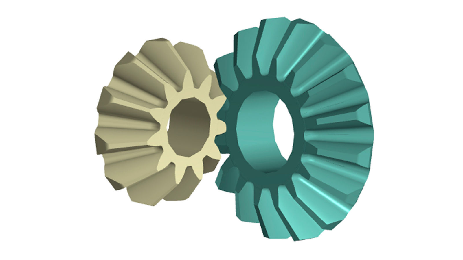

Design and Load Capacity of Crown Gears in Comparison to Bevel Gears
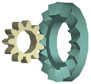
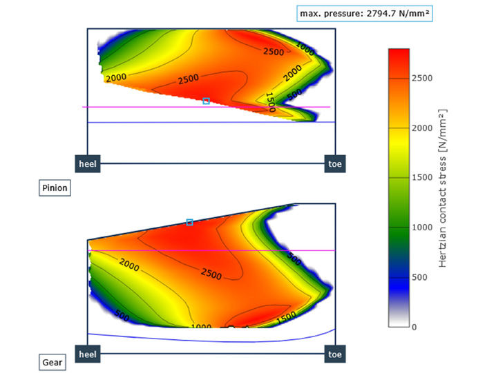
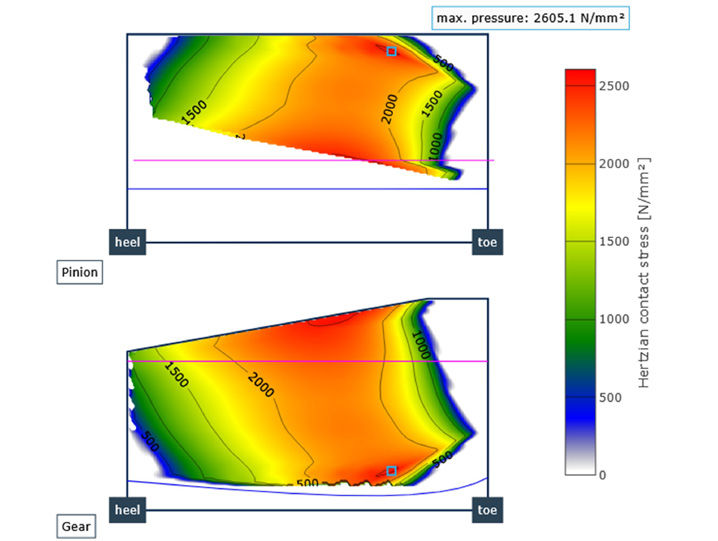
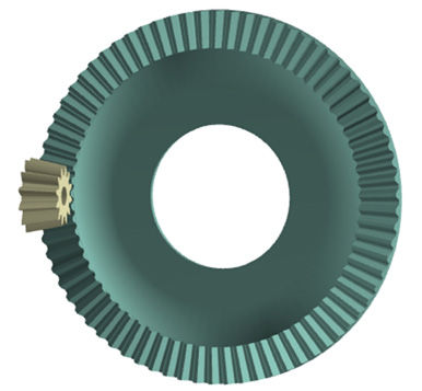
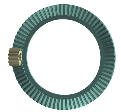
Compared to bevel gears, crown gears (also known as face gears) have some clear advantages. One of the most important is the axial freedom of the pinion. Therefore, it is not necessary to position the pinion at the exact mounting distance, and there is freedom from axial forces on the pinion side, at least as long as a spur gear is used as the pinion. On the other hand, there is a certain limitation of face width. Depending on the gear ratio, the beginning of the tooth root fillet of the crown wheel runs towards the tooth tip if the inner diameter becomes too small. The top land becomes too narrow if the outer diameter is too big. This limitation may lead to high Hertzian pressure on the tooth flank. It is therefore essential to calculate the load-carrying capacity of crown gears as accurately as possible, ideally using the same calculation methods that have been established for bevel gears for many years. As soon as this is carried out, there will be a clear answer if the usage of a crown gear is possible or whether a bevel gear set is to be preferred.
Development Process for Bevel and Crown Gears
Spiral bevel gears, in particular, have special features that prevent a simple design. Although it is certainly possible to estimate the load capacity of bevel gears as a first step, just by using macrogeometry data with the aid of standardized calculations. The microgeometry cannot be described with the aid of simple deviations from an involute profile, as is the case with cylindrical gears. This led to the development of flank generators many years ago, with which a manufacturing simulation can be carried out from the machine setting data and precise tool profile data. All points of the flank and tooth root can be determined in three dimensions. As soon as the results for the pinion and wheel are available, the flank data generated in this way can be virtually paired and rolled without load. From this load-free tooth contact analysis (TCA), contact patterns, rotational errors, and ease-off can be derived as representations of the effect of crowning in the load-free state. These results already provide a lot of information on the sensitivity of the contact pattern position and the running behavior.
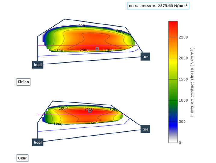
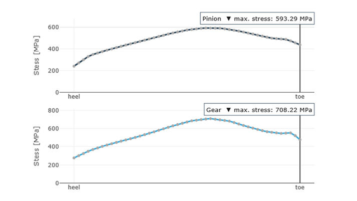
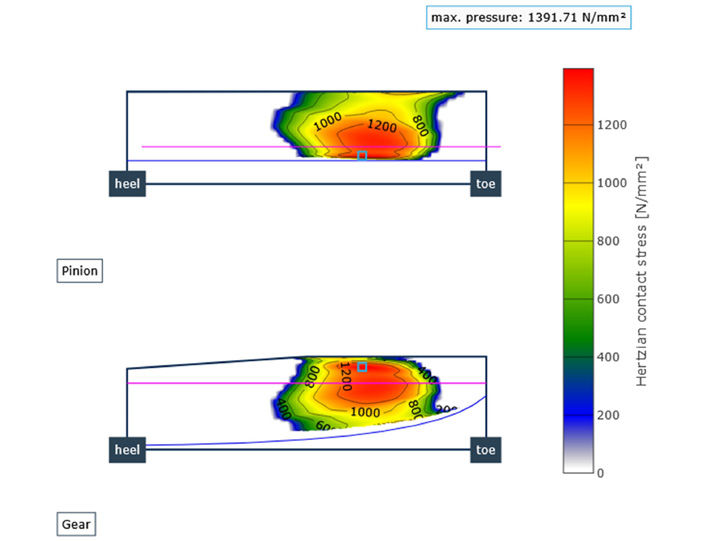
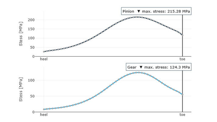
In a further step, a TCA under load is usually connected. In this final step, not only are the local pressures and tooth root stresses determined, but local load capacity values can also be calculated for the flank and root. If the calculations are based on a load spectrum, local damage sums can also be determined. If axis displacements in the gearbox were calculated in advance and for the respective loads using CAE software, these displacements can be easily accounted for in the TCA under load. This ultimately results in realistic load-bearing patterns under load and the corresponding load capacities. If necessary, the microgeometry can be optimized in a development loop so that optimum load capacities are ultimately achieved.
This approach has been used for many years in the development of spiral bevel gears, whereby the manufacturing simulation, in particular, was predominantly tied to software from the well-known bevel gear machine manufacturers. With the help of independent software tools that use flank generators for practically all conceivable gear types, it has also been possible for some time to carry out ease-off calculations for spur bevel gears. Since the relevant loaded tooth-contact analysis (LTCA) software tools are no longer tied to internal flank generators for spiral bevel gears but instead use point clouds provided by the flank generators as input data, TCA under load can now also be carried out easily, e.g., for differential bevel gears (see Refs. 1 and 2). In a further step, these possibilities have now been transferred to many other types of gears, so that the procedure described above can now also be applied to the development of crown gears (Ref. 3). Since the same tools are now used to determine the load capacity, the results calculated for crown gears can be compared 1:1 with the results for bevel gears. This allows us to directly compare advantages and, where applicable, disadvantages of crown gears compared to bevel gears for specific applications. This is shown in the following two examples.
Examples
Example 1: Differential Gear Set
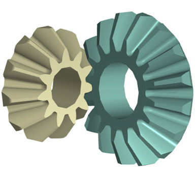
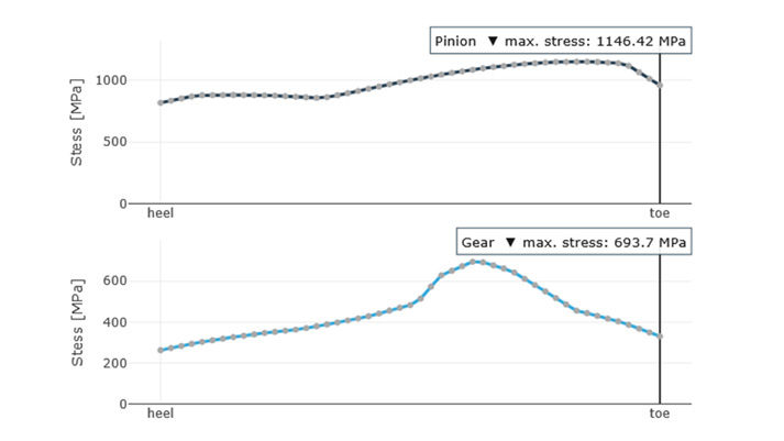
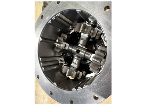
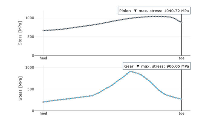
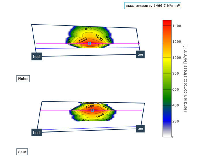
The first example is a differential gear that was initially designed as a classic forged bevel gear differential, with modified tooth root on toe side. While differentials were largely inconspicuous with classic drive technology, the situation with regard to the requirements for differentials has changed fundamentally with the increasing introduction of hybrid and electric drives. In particular it should be emphasized that due to the recuperation mode and the increased drive power when cornering, e-drive solutions also lead to significantly higher torques. Above all, this means that the very high Hertzian pressures on the flanks no longer occur predominantly only when driving straight ahead and thus when the differential is stationary, but also when cornering. This leads to a significantly higher risk of flank damage such as pitting or flank breakage.
Following the macrogeometry data for the original bevel gear design:
- Number of teeth: Pinion z1 = 11, gear z2 = 16
- Mean normal module: mmn = 3.792 mm
- Face width: b = 22 mm
- Ball diameter: de = 80 mm
- Pressure angle: an = 22.5°
- Two output bevel gears, four planets (pinions)