



Differentiating Noncircular, Elliptical, and Oval Gears
Are noncircular, elliptical, and oval gears all the same thing?
Noncircular Gears
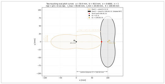
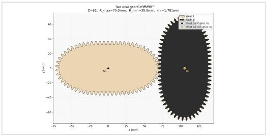
Noncircular gears are found as early as the sketches of Leonardo da Vinci in his Codice Atlantico, documenting his work from 1478 to 1519. The gear community is, of course, familiar with this; refer to, e.g., Aaron Fagan’s Addendum column “Noncircular Gears: The Unicorn of Machine Technology” in the June 2022 issue of Gear Technology. Their use is limited; they are a niche component due to their complexity of design and manufacturing. The advent of servo motors solved the problem of controlled motion in a more general approach, reducing the need for noncircular gears further. Still, they remain high-performing mechanical solutions. The dedicated book by Faydor L. Litvin et al, Noncircular Gears: Design and Generation (Cambridge University Press, 2009), is widely known and gives a dense overview of the topic. In the context of this paper, we will limit the observations to convex elliptic, Figure 2 and oval gears Figure 3. Gears 1 and 2 have the same properties.
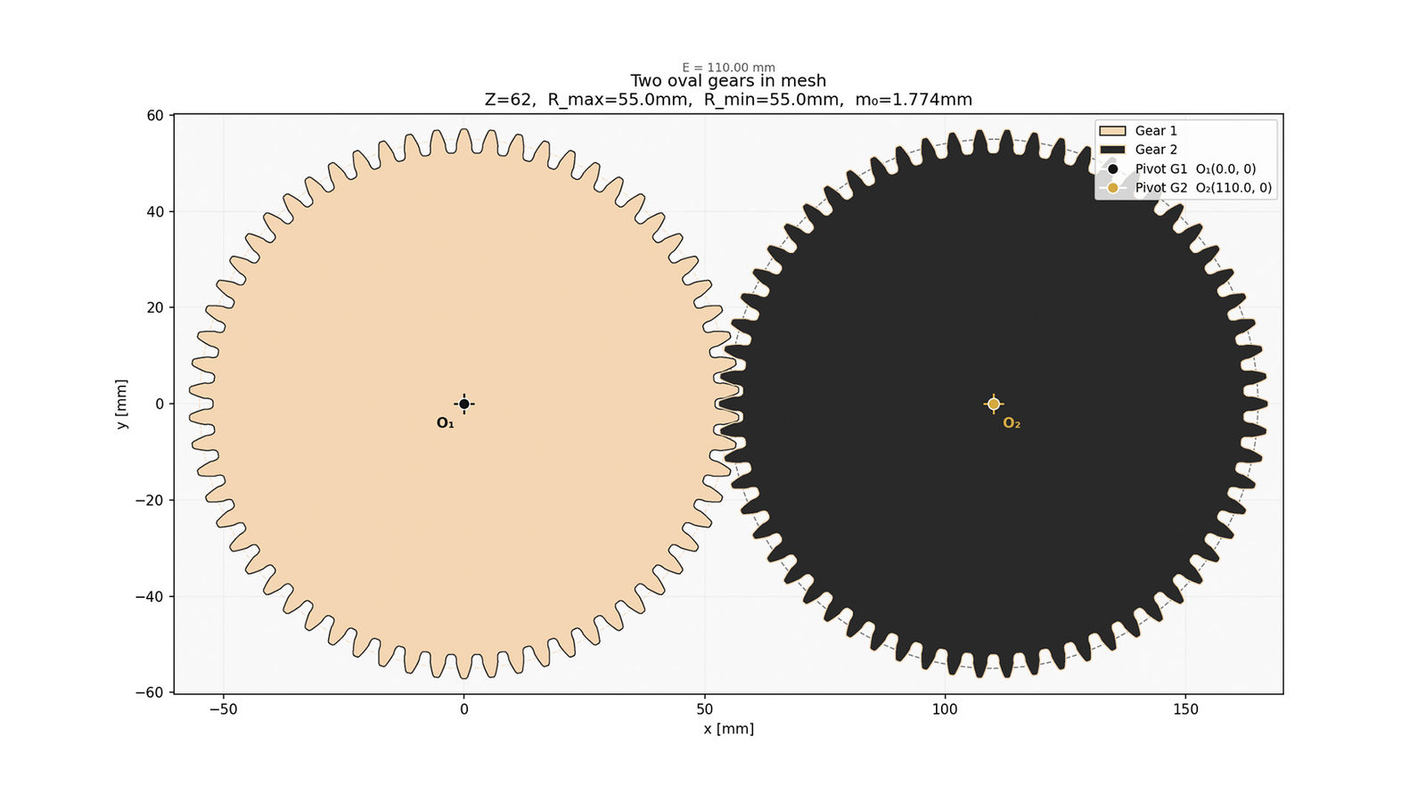
These two types of noncircular gears transform motion between parallel axes, where a continuously changing transmission ratio results within a single revolution. Unlike linkage mechanisms but similar to cam-follower mechanisms, elliptical and oval gears provide a compact arrangement for delivering periodic speed variations, making them suitable in e.g., packaging systems, textile machines, flow meters, or heavy press machines, with a slow working stroke and a fast return stroke. This document focuses on the differences between elliptical gears and their oval cousins. In extremis, both are transformed into circular gears, Figure 1.
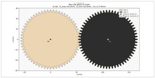
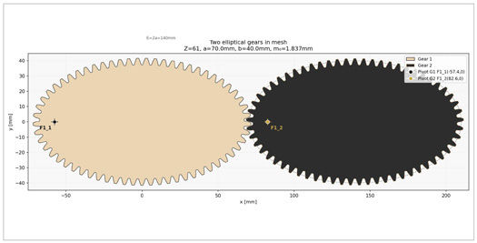
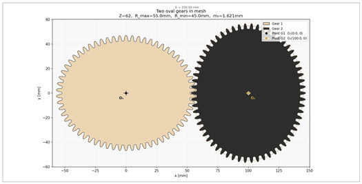
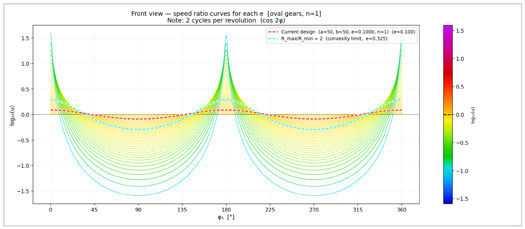
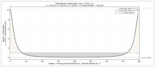
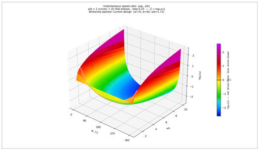
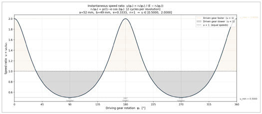
The defining feature of noncircular transmissions is the momentary (instantaneous) ratio i. In circular gears, the ratio i is constant and may be determined from the number of teeth, Figure 4. In elliptical, Figure 5, and oval gears, Figure 6, it is a continuous function of the polar angle of rotation φ: i(φ) = ω2 / ω1 = r1(φ) / r2(ψ). With the sum E = r1 + r2 = constant, the ratio is a function of the driver’s radius alone i(φ) = r1(φ)/(E - r1(φ)).
Circular Gears Rotate Around Their Centers
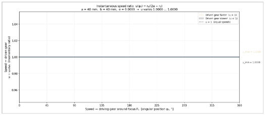
Obviously, the ratio of two circular gears is constant, and while trivial, the momentary ratio is shown in Figure 4 for reference.
Elliptical Gears Rotate Around the Focal Point
The elliptical gear is defined by a pitch curve (centrode) as a standard ellipse. A significant kinematic difference exists in circular gears rotating around an eccentric axis: to maintain a constant center distance E while rolling without slip, a pair of identical elliptical gears must rotate about one of their foci, O1 or O2, rather than their geometric centers O, as with circular gears.
This requirement stems from a geometric property of the ellipse that for any point on the pitch curve, the sum of the distances to the two foci is constant and equal to the major axis length 2 * a. When the rotation centers are placed at the foci, the sum of the instantaneous radii of the two ellipses, r1 + r2, equals the axial distance E = r1(φ) + r2(ψ), φ and ψ being the rotational angles of the two ellipses. For identical elliptical gears where one revolution of the driver corresponds to one revolution of the driven gear, the center distance is E = 2 * a, where a is the major axis length.