[advertisement]
Technical Articles

July 11, 2025


Technical

Electric vs. Combustion: A Comparative Analysis of Gear Design for Commercial Vehicle Applications

The evolution of automotive technology has ushered in a new era where the traditional internal combustion engine (ICE) is gradually giving way to electric vehicles (EVs). This transition is not without its engineering challenges, particularly in the domain of gear design. ICEs and EVs have fundamentally different requirements for gearboxes, which are pivotal in translating engine power into motion. ICE vehicles require complex multi-speed transmissions to accommodate a narrow band of optimal engine speeds, while EVs benefit from simpler, fewer number of speeds gearboxes due to the electric motor’s ability to deliver consistent torque across a wide range of RPMs (Ref. 1). Firstly, we would shed some light on how ICE vehicles transitioned to EVs in the commercial segment, discussing various powertrain layouts and potential gearbox configurations. Then we will present a comparative study of different gear parameters between ICE and EV gear design and explore the impact of EV gear design on manufacturing processes. Finally, we will present a case study focusing on a 14-ton commercial vehicle (Class 7), comparing a multi-speed ICE gearbox to an EV central drive single-speed reduction gearbox. For this comparison, we assume the vehicle operates at the same output speed and torque requirements. The case study aims to provide practical insights into the application of EV gear design in real-world scenarios.

General Architecture Comparison of an ICE and EV Gearbox

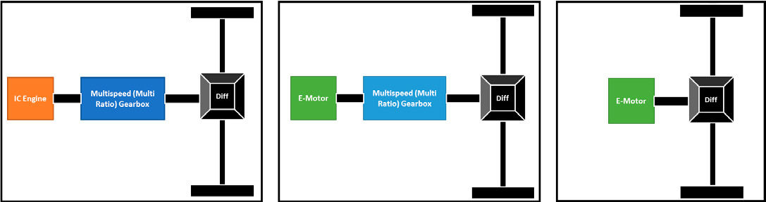
A typical ICE powertrain layout, as illustrated by the block diagram of Figure 1a, is comprised of an engine, a gearbox, and a rear drive axle. For a 14-ton vehicle, a multi-speed (5 or 6 speed) gearbox is generally necessary. Some commercial vehicle manufacturers have initiated the transition to Electric Vehicles, adopting a retrofit approach. This involves replacing the ICE with an electric motor while keeping the rest of the powertrain the same (Ref. 2) as illustrated in Figure 1b. While this approach could potentially reduce initial costs and prolong the lifei of the existing fleet, it may not yield the most efficient solution, even with adjustments to the gearbox (Ref. 2) An alternative approach would be to replace both the ICE and the multi-speed gearbox with a high-torque, low-speed electric motor to directly drive the rear axle as illustrated in Figure 1c.

Figure 1—Powertrain layouts.

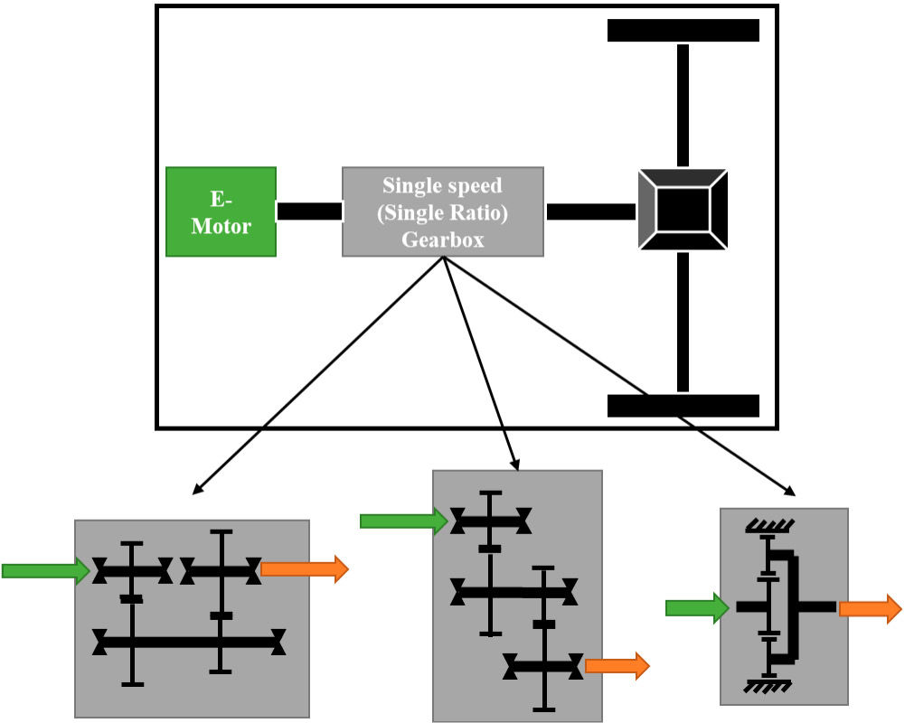
Building on the concept of optimizing electric powertrain layouts, a more effective solution for an 8–14-ton central drive layout emerges. This solution, as shown in Figure 2, uses a power-dense, high-speed (>10,000 rpm) motor coupled with a single-speed reduction gearbox. System analysis shows that a single gear ratio is sufficient to meet the startability, gradeability and top speed requirements of 8–14-ton vehicles. Because of a single reduction ratio gearbox and a high-speed motor, the overall powertrain becomes power-dense. A comparative study between the direct drive layout and a motor with a single reduction ratio gearbox showed a 300 percent weight improvement in the powertrain. Now this single-speed gearbox can further have different configurations as shown in Figure 2.

Figure 2—Central drive system with different gearbox configurations: (a) Coaxial input/output with offset gear layout; (b) Offset input/output with countershaft layout; and (c) Coaxial input/output with planetary layout.

In addition to the aforementioned powertrain layouts, another viable option is the e-beam layout. In this configuration, the motor and the reduction gearbox are integrated into the vehicle axle as shown in Figure 3. This design eliminates the need for a propeller shaft and the final drive ratio becomes a part of the overall gearbox ratio. There are several ways to achieve this configuration. One possibility is a parallel axis offset reduction gearbox. where the ratio can be achieved in stages. Another option is a compound planetary system, where the ring is fixed, and the carrier is integrated into the differential case. A third option could be a combination of a parallel axis gear set with a planetary reduction set. There are numerous other configurations that can achieve the same ratio. Each of these configurations has its own advantages and disadvantages. The optimal layout can be selected based on a variety of factors, including available space, target volume and weight, cost, efficiency, and complexity.

Figure 3—E-beam layout with different gearbox layout: (a) Offset input motor with countershaft layout; (b) Coaxial input output Layout with planetary gear reduction; and (c) Offset input motor with planetary layout.

Gear Design Comparison for ICE and EV

The primary objective of the transmission gear design is to meet the durability as per the transmission product life requirement. This is achieved by ensuring sufficient safety factors against potential failure modes. The major failure modes in transmission gears, bending and pitting, are fatigue failures that develop over time due to repeated cyclic loadings on the gear teeth during the service life of the transmission. Industrial standards like ISO 6336 (Ref. 3), AGMA 2001-D04 (Ref. 4) are generally used for the rating of gears at the design phase, so that the designed gears would have sufficient life to meet the product requirement. These rating standards estimate the safety factors by comparing the life requirement from the application to the available life calculated from the stresses under operating loads using a defined S-N curve of the gear material used. The gear’s loading pattern changes when the power source shifts from an internal combustion Engine to an electric motor. Although electric motors can provide a more stable torque input to the transmission compared to ICEs, certain characteristics of electric motors, such as bidirectional operation and regeneration, influence the loading pattern on gears. These characteristics require special attention from gear engineers to achieve the desired gear performance.

In conventional ICE transmissions, the gears rotate only in one direction, as the engine rotation direction cannot be reversed. Therefore, the primary design focus is mainly on the drive flank, which bears the load when the engine propels the vehicle. The coast flanks of the gears are loaded only when the vehicle is coasting, and these loads are typically smaller than drive loads. Exceptions to this include reverse idler gears and planet gears of planetary systems. In these cases, both flanks are loaded during normal operation as they are engaged in multiple gear meshes simultaneously. Splitter gears in certain transmission architectures are special cases where the drive and coast flank get interchanged depending on the gear selection. One of the most important features of electric vehicles over ICE vehicles is regenerative braking. During this process, the motor operates as a generator to recover the braking energy. As power flows in the opposite direction during regeneration, while the driveline rotation direction remains the same, the coast flank of the gears transmits the load. This makes the design of both drive and coast flanks equally important in EV gear design. Therefore, the overall gear reliability is the product of drive flank reliability and the coast flank reliability. Since the motor can operate in both rotational directions, reverse gear is achieved just by reversing the motor direction. This is another case where both the gear flanks transmit load in EV gearboxes.

Share and save:


This article appeared in the July 2025 issue.


Read PDF

[advertisement]

For cases like reverse idler or planet gears where the gear teeth are loaded in both directions in every rotation, the gear rating standards (Refs. 3, 4) recommend a 70 percent reduction in bending safety factor. ISO 6336-3 Annex B calls it the mean stress correction factor Ym, which considers the influence of working stress conditions other than pure pulsations. An electric vehicle gear gets a fully reverse loading in instances when the motor switches between motoring and regeneration. The loading of EV gear teeth with regeneration is given in Figure 4. The Ym factor for periodic load reversals, as in electric vehicles, should be between 1 and 0.7, depending on the number of load reversals. Turci (Ref. 5) investigated various methods to account for similar loading patterns of hybrid vehicles in bending calculation and gives reference calculations from the gear design book (Ref. 6) for estimating Ym from the number of load reversals.

Considering that, Ym for no load reversal is 1 and full load reversal is 0.7, the Ym factor for periodic load reversals with the number of load reversals as Nrev is given by:

For, and

For,  

Figure 4—Gear tooth loading pattern with periodic load reversals (Ref. 6).

The loading pattern considered for the calculation, as per Ref. 6, is given in Figure 4. The number of load reversals needs to be estimated from detailed duty cycle data. This data can be derived from data collection on a similar application or from a simulation performed with appropriate driving cycle and vehicle parameters. It is important to note that the equation takes into account a full reversal load, which means the magnitude of the loading is identical in both directions.

Consideration of reverse loading in bending safety factor calculations using the appropriate Ym factor ultimately results in lower allowable bending stress levels in EV gears compared to ICE transmission gears with similar bending life requirements. The active use of both the flanks of the gear teeth during operation in an EV transmission demands higher quality levels and good manufacturing control on both gear flanks of EV gears compared to ICE transmission gears.

Gear Microgeometry Comparison for ICE and EV

In an ICE vehicle that has a multi-speed gearbox, each gear stage has a range of torque at which it operates, so each gear pair can have optimized microgeometry for that torque range. For gears that operate at high torque, larger microgeometry modifications, such as tip relief and profile crown, are typically needed to compensate for the tooth deflection, whereas for low torque, higher speed gear pairs, the modifications are relatively smaller. The below figure illustrates the microgeometry comparison of gears of different ranges from a multi-speed gearbox. The first gear operates at high output torque and low speed and as the gear number progresses, the output torque reduces and the speed increases. With decreasing torque, the amount of involute modification decreases. In an EV single-speed gearbox, the same gear pair takes the complete range of torque from the electric motor. So, one approach could be to optimize the microgeometry modification for the torque range in which the vehicle operates for the longest duration. Generally, this maximum operation occurs at torque levels close to or less than the continuous torque of the electric motor. In this case, smaller microgeometry modifications may be required for the EV gears. Along with this, the tolerance band applied to the microgeometry is also higher for ICE gears, whereas it is tightly controlled for EVs to reduce the effect of manufacturing variation on noise.

Figure 5—Illustration of Involute modifications of: (a) different gears of a multi-speed gearbox and (b) gear of a single-speed gearbox.

Comparison of Gear Performance

In this section, we would like to compare various gear parameters like efficiency, NVH, micropitting and scuffing, and how the results compare for an ICE and EV gear design. Efficiency and NVH are two contradictory critical quality parameters of gears, and the design must maintain a balance between both. The design cannot be optimized for efficiency and NVH independently; it must be done conjointly. The high-speed operation of gears in EVs has increased the risk of micropitting and scuffing, so we have discussed what can be done to minimize this risk.

Efficiency

Efficiency is one of the most important parameters in EVs as it directly influences the vehicle’s range, which is a critical factor in product marketability. The overall powertrain efficiency is driven by efficiencies of various components, including the motor, inverter, gears, bearings, seals and auxiliary components like the pump and heat exchanger. Every component should operate at its optimum efficiency to improve the overall vehicle performance. Thus, it is important to design gears for high efficiency. Gears with shorter tooth height typically exhibit higher efficiency; however, they tend to perform poorly in terms of NVH. Therefore, gear design involves a tradeoff between maximizing efficiency and minimizing NVH. Figure 6 compares the calculated efficiency of an ICE drivetrain and an EV drivetrain across a range of operating speeds. Efficiency values are determined per ISO 14179-2 (Ref. 7).

Figure 6—Efficiency comparison for ICE and EV.

Figure 6 compares total power loss, which is the sum of load-dependent and speed-dependent losses. The ICE gearbox has splash lubrication and uses high viscosity oil, whereas the EV has forced lubrication and uses lower viscosity oil. In EV, it is preferred to have forced lubrication to avoid churning loss and have baffles around gears to ensure mesh lubrication. At lower speed in an EV, the total loss is less than in an ICE because of lower module and lower surface roughness of gears. As speed increases, the difference in loss between ICE and EV increases further because of more churning or speed losses in ICE as it uses high viscosity oil and has many components dipped into the lubricant.

NVH

[advertisement]

While striving to maximize efficiency, it is equally important to evaluate NVH concurrently. The contact ratio is one of the most important parameters determining gear tooth excitation and, thus, gearbox noise level. The primary source of gear noise, often referred to as whine noise, in a gearbox is the peak-to-peak transmission error and its harmonics (Ref. 8). In ICE vehicles, the engine noise would mask most of the other noises coming from the gearbox and thus gear noise is not as critical as it is with EVs (Ref. 2). In EVs, the motor operates quietly, allowing other noises to become more noticeable, making NVH a significant challenge. A comparison of the PPTE, in a quasi-static condition and over the operating torque range in Figure 7, shows that the values are reduced to less than half for EV gears compared to ICE gears. The reduction is different for different torque values, as the microgeometry is optimized for torques that operate for the maximum duration of operation. If we convert the improvement to a dB level with ICE as baseline, an average of 6dB of improvement can be achieved with this reduction (Ref. 9). This can be achieved by designing higher contact ratio gears while maintaining efficiency targets. The contact ratio should be such that it minimizes the variation of mesh stiffness over the meshing cycle. Reducing gear mesh stiffness variation ultimately reduces the peak-to-peak transmission error and, in turn, the TE harmonics.

Figure 7—PPTE and 1st Harmonic comparison for ICE and EV.

As EV operates at higher input rpm, to quantify the effect of speed on noise, we have compared the dynamic TE over a vehicle speed of 0–60 kmph and its combined effect on the resultant dynamic forces acting at the bearings. Figure 8 shows that the dynamic TE in EV is maintained to less than one-third of that in ICE, thus significantly lower resultant dynamic forces are observed at the bearings. At higher frequencies, the first harmonics of the resultant dynamic forces are a bit higher, but still, the peaks of EV are much smaller in magnitude than the ICE. So, in EV, it is important to minimize static as well as dynamic transmission error, as the input speeds in EV are much higher compared to ICE. As the nominal value for TE reduces, even small variation in TE leads to higher variations in sound pressure level (SPL). So, the gear design should be robust enough that the TE is least sensitive to manufacturing errors to minimize variation in SPL.

Figure 8—Dynamic TE and Resultant Dynamic Force comparison for ICE and EV.

Micropitting and Scuffing

Micropitting occurs when the lubricant film thickness is insufficient relative to the surface roughness of the gears. Factors such as high temperatures, low oil viscosity, and excess load can lead to reduced film thickness. The smaller the ratio of surface roughness to lubricant film thickness, the greater the likelihood of micropitting. Increasing the ratio of surface roughness to lubricant film thickness is one of the most effective preventative measures against micropitting (Ref. 10). The following analysis shows the effect of oil viscosity and surface roughness on lubricant specific film thickness.

In ICE transmissions, high-viscosity oil is typically used, and surface roughness is higher compared to EVs. Figure 9 shows a comparison of the minimum specific film thickness in ICE and EV gears at a vehicle speed of 60 km/h. In EVs, low viscosity oil is commonly used to improve efficiency, but if the same level of surface roughness is maintained in EVs as in ICE, then the specific film thickness degrades, increasing the risk of micropitting. To maintain the same level of specific film thickness in EV as in ICE, an improvement in gear surface roughness is necessary to help lower the risk of micropitting issues. Therefore, to improve the gear mesh efficiency and prevent micropitting with low viscosity oil, a superior surface roughness should be maintained in EV gears.

Figure 9—Comparison of the risk of micropitting.

Scuffing is a localized damage to the gear teeth resulting in matte and rough finishes of the contacting surfaces, along with changes in tooth form. This type of damage generally occurs in the tooth contact zone, where contact pressure and sliding velocity are high, far from the pitch line. In EVs, gears are designed for a higher contact ratio, resulting in high sliding velocities, which can increase the risk of scuffing. As a severe adhesive wear phenomenon, scuffing occurs when the oil film thickness between the tooth contacting surfaces is not enough to prevent metal-to-metal contact, which causes local welding and subsequent tearing (Ref. 11). So, to avoid the risk of scuffing in EV gears, lubrication design should ensure sufficient lube flow, cooling, and film thickness formation at the contact location.

Effect on the Manufacturing Process and Gear Inspection

ICE gearboxes, with their more complex designs, typically involve more components and assembly processes, which can increase manufacturing complexity and cost. On the other hand, required gear tolerances are not as stringent as in EV applications. Whereas manufacturing the simpler design of EV gearboxes can lead to overall reduced production costs, although the materials used must be carefully selected to withstand the high number of load cycles. Also, the surface roughness on EV gears is much less than ICE gears, which calls for polishing after grinding. This impacts tooling cost and manufacturing cycle time. Planetary gear reductions, and more specifically compound planetary gears, are used in EV applications to reduce the gearbox volume and best fit the vehicle’s powertrain envelope. The machining of such gears is difficult and needs operations like skiving and honing. Since NVH is a critical requirement, a single-flank roll test is recommended at the end of line testing to maintain product quality. All these machining requirements require significant initial investment and know-how. So, even though the gearbox complexity has reduced, component design has become complex, which could lead to increased manufacturing costs.

Conclusion

Designing gears for electric vehicles requires a delicate balance between achieving high efficiency and maintaining low NVH. To attain high mesh efficiency, gears should be fine ground or even polished, depending on surface roughness requirements. This approach also helps mitigate the risk of micropitting. With the use of low viscosity oil, the risk of micropitting and scuffing increases, requiring a lubrication design that ensures sufficient oil delivery to the gear mesh. For low NVH, the transmission error (TE) values should be minimized, and the design should be robust to manufacturing variations. From the manufacturing perspective, existing machines and tooling may require updates and enhanced process control will be required to minimize variations.

Overall, the transition to electric mobility is driving innovation in gear design, with a focus on optimizing efficiency, reducing weight, and minimizing noise and vibration. As the automotive industry continues to evolve, the gear design for both ICE and EVs will undoubtedly continue to adapt to meet the unique requirements of each powertrain technology.

In summary, the design of gears for high-speed electric motors is a complex endeavor that requires a careful balance of material science, mechanical engineering, and precision manufacturing. As electric vehicles continue to gain popularity, the demand for high-performance, reliable, quiet and efficient gear systems will only increase, presenting ongoing challenges and opportunities for innovation in this field.

Acknowledgement

The authors thank Eaton–Mobility Group for their support in the development of this paper.

References

  1. B.R Hohn, Y. Zhang, AGMA FTM 2023, “How Many Speed Ratios for Electric Cars? One Example.”
  2. Xu, Y., “Development of Commercial Vehicle E-Axle System Based on NVH Performance Optimization,” SAE Technical Paper 2020-01-1421, 2020. doi:10.4271/2020-01-1421.
  3. ISO 6336-1:2019, “Calculation of load capacity of spur and helical gears–Part 1: Basic principles, introduction and general influence factors.”
  4. ANSI/AGMA 2001-D04, “Fundamental Rating Factors and Calculation Methods for Involute Spur and Helical Gear Teeth.”
  5. Massimiliano Turci, “Design and Optimization of a Hybrid Vehicle Transmission,” Gear Technology, May 2019.
  6. Linke, H. 1996, Stirnradverzahnung–Berechnung, Werkstoffe, Fertigung; Ed. 1, Hanser, Munchen.
  7. ISO 14179-2:2001, “Gears Thermal Capacity–Part 2: Thermal load-carrying capacity.”
  8. Munro, R.G. and Houser, D., “Transmission Error Concepts,” The Ohio State University Gear Lab, 2002.
  9. ISO 3745:2003, “Acoustics–Determination of sound power levels of noise sources using sound pressure–Precision methods for anechoic and hemi-anechoic rooms.”
  10. ISO/TS 6336-22:2018, “Calculation of micropitting load capacity of cylindrical spur and helical gears–Part 1: Introduction and basic principles.”
  11. C. H. Wink, AGMA FTM 2011, “AGMA 925-A03 Predicted Scuffing Risk to Spur and Helical Gears in Commercial Vehicle Transmissions.”
First presented at the 2024 Fall Technical Meeting (FTM), October 7–9, 2024, Rosemont, IL. Printed with permission of the author(s). Statements presented in this paper are those of the author(s) and may not represent the position or opinion of the American Gear Manufacturers Association.
[advertisement]