Once the design of a new gear set is complete, all requirements for strength, service life, efficiency, and noise appear to have been met. At this point, the design engineers’ job is done—but is it really?
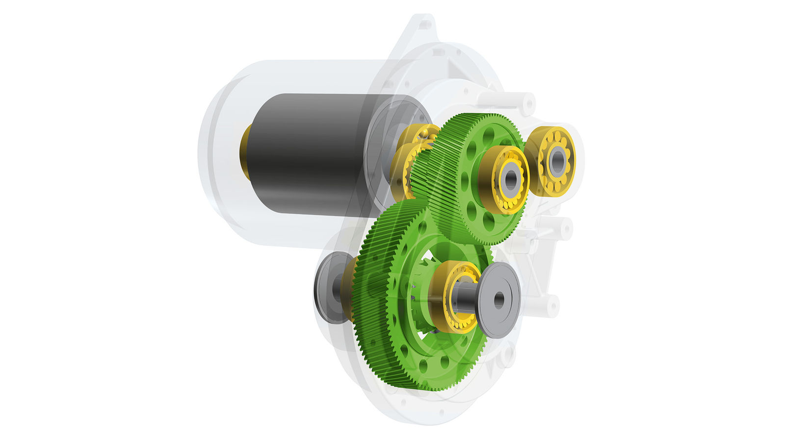
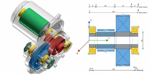
Manufacturing follows the design stage. Many design engineers assume that this step requires little attention. However, this can lead to problems, additional costs, or delays later. Figure 1 shows an example of a typical two-stage EV drive. The idler shaft has two gears, and the original idea was to manufacture it as a single piece. However, the pinion of the second stage is very close to the gear of the first stage. Hobbing teeth on the pinion in this position is not possible. Power skiving may also be unsuitable because optimal process parameters might not be achievable. One possible solution is to mount the gear after the pre-finishing step. Because of precision and noise requirements, the finishing step should be performed with the gear mounted. The same challenge arises for applying honing processes, as there is very little space available.
Even this simple design poses challenges for manufacturing and process engineers. This highlights the importance of considering manufacturing early in the design stage. It is not necessary to define every detail at this stage, but sufficient consideration should be given to avoid common manufacturing pitfalls.
KISSsoft is a comprehensive gearbox design software from Gleason Corporation. Since version 2025, an increasing number of features have been added to address typical manufacturing questions. The following sections highlight some of them. The first feature addresses the interference problem when cutting teeth. The hobbing process can now be modeled directly in the cylindrical gear calculation, with the option to define an interfering feature on either side of the gear.
Figure 1–Example of an intermediate shaft. (All images: KISSsoft)
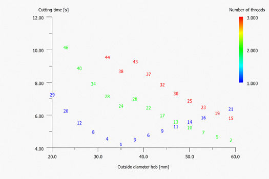
The built-in fine-sizing function of the hobbing process module systematically varies the outer diameter, the number of threads, and the number of gashes. It checks compliance with gear quality requirements, including the generation of flats and feed marks, as well as interference conditions. It then estimates the cutting time and usable tooth length. Figure 2 shows the resulting solutions, identified by their index in the results table, plotted as cutting time versus outer diameter, with the number of threads indicated by color.
Figure 2—Cutting time versus hob outer diameter, for one-, two- and three-threaded hobs.
For a given number of threads, increasing the outer diameter results in a higher number of gashes, allowing a larger axial feed rate. On the other hand, a larger diameter combined with a fixed cutting speed results in a lower rotational speed of the tool and the gear. A larger diameter also increases the approach distance. As a result, there is an optimal diameter that achieves the shortest cutting time.
More threads typically require a larger diameter because the number of cutting edges per gear tooth equals the number of gashes divided by the number of threads. To achieve the required quality, more gashes are therefore necessary. This explains why the solutions with two and three threads are shifted to the right. They show the same trend: increasing axial feed and decreasing cutting time as the outer diameter of the tool increases. However, because of the defined interference conditions, the maximum possible tool diameter is reached before the optimal cutting time is achieved. In this case, a single-thread hob results in the shortest cutting time.
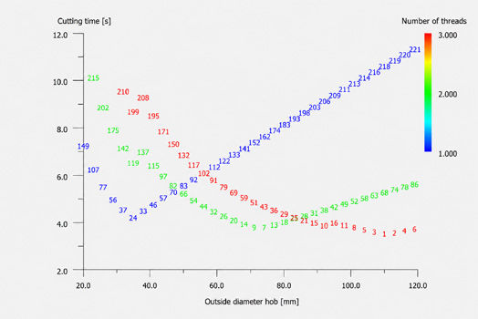
To illustrate the general trend more clearly, Figure 3 shows the fine-sizing results for the same case, but without any interfering features. Optimal hobs with two and three threads are also feasible and appear among the possible results. In this case, they would slightly reduce the cutting time, with an estimated reduction of about 10 percent.
Figure 3—Cutting time versus hob outer diameter, for one-, two- and three-threaded hobs, for very large outer diameters.
Cutting time can be converted into machine hours, which directly affects costs in a mass-production environment. In addition, the cost of the tool itself is another component of the overall production cost.
A larger diameter allows a greater number of gashes and/or a longer usable tooth length (UTL) on the hob. More gashes reduce wear and enable more parts to be cut before the hob requires resharpening. A longer UTL allows more resharpening cycles before the hob reaches the end of its service life, thereby increasing the tool’s total service life. On the other hand, the initial price of a hob also depends on its size. If a linear relationship with the number of gashes is assumed, because grinding a hob with more teeth requires additional processing, the cost increases linearly. If a constant weight-based price is assumed, the increase is proportional to the square of the diameter, provided the hob length remains constant. Therefore, the hob price can be expected to increase somewhere between linearly and quadratically with its diameter.
Table 1 compares two hobs. The diameter of the second hob is 50 percent larger than that of the first. For the first hob, a tool price of 1,000 is assumed, while the second hob is assumed to cost 1,875, the mean value between 150 percent and 225 percent. For resharpening, costs of 50 for stripping, 150 for sharpening, and 100 for recoating are assumed. Under these assumptions, the resulting cost per part is 0.048 for the first hob and 0.035 for the second. In this case, over the entire service life of the tool, the larger and significantly more expensive hob is the more economical solution. Of course, the result depends strongly on the specific circumstances, particularly the tool and resharpening costs, and other cases may lead to different outcomes.
Hob
#1
#2
Outer diameter (mm)
27
41
[advertisement]
Number of gashes
8
12
Tool costs
1000.00
1875.00
Stripping costs
50.00
50.00
Sharpening costs
150.00
150.00
Coating costs
100.00
100.00
Total conditioning costs
6600.00
6900.00
Usable teeth
245
365
Tool life per tooth (m)
4.800
4.800
Cutting length per part (m)
0.170
0.170
Parts per conditioning
6917
10305
Number of conditionings
22
23
Parts per tool
159091
247320
Tool cost per part
0.048
0.035
Table 1—Cost calculation for two hobs of different sizes.
Once the feasibility of the hobbing process has been confirmed, it is typically followed by grinding or another hard finishing process. Therefore, some stock is left during pre-finishing. This stock is often defined using typical values derived from experience. To go beyond experience alone, software can be used to investigate the resulting final tooth form in greater detail.
The rollout graphics in KISSsoft show the pre-finished tooth form for three material conditions: minimum, maximum, and a user-defined condition, which is typically between the other two, such as the mean value. This feature makes it possible to evaluate how stock and pre-finishing tolerances influence the finished tooth form, particularly the tip and root form diameters.
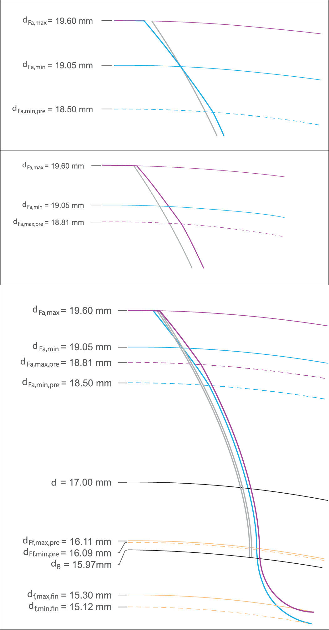
Figure 4 shows an example of such a rollout graphic with the maximum and minimum material conditions. To make the details easier to see, the upper-left section shows only the tip area for the minimum material condition, while the upper-right section shows the same area for the maximum material condition. Two profiles from the pre-finishing step are shown: the maximum-condition profile is pink, and the minimum-condition profile is light blue, with the defined stock tolerance between them. The two gray profiles on the left are involutes corresponding to the grinding step, and the finished tooth-thickness tolerance determines the distance between them.
Figure 4—Rollout graphic for the whole profile (bottom), the tip area in minimal stock tip condition (top), and the tip area in maximum stock condition (middle).
This example shows a gear with a tip chamfer generated during pre-finishing with a semi-topping tool. The finishing step removes part of the chamfer. The point at which the chamfer begins on the profile defines the tip form diameter.
The tip form diameter decreases as less material is removed during finishing. Accordingly, the minimum-stock condition determines the minimum tip form diameter, shown in the figure as the light-blue solid circle. The dashed circle indicates the start of the chamfer on the pre-finished tooth form and is included for reference.
The maximum stock condition, which corresponds to the greatest amount of material removed during finishing, results in the largest tip form diameter. In this case, the entire chamfer is removed, so the tip form diameter coincides with the gear’s tip diameter. Assessing these extremes is critical because variations in the tip form diameter can affect tooth contact, load distribution, and overall gear performance.
The permissible limits for the tip form diameter depend on the specific application. A smaller diameter may reduce the transverse contact ratio. However, if too much material is removed, as in this case, the chamfer may be eliminated. Ultimately, the designer must define the appropriate range of values.
Moving from the tip to the root, the next parameter to check is the root form diameter. The primary concern is to ensure that the root form diameter, true involute form (TIF), is smaller than the start of the active profile (SAP). If this condition is not met, contact with the mating gear is likely to occur in the non-involute root area.
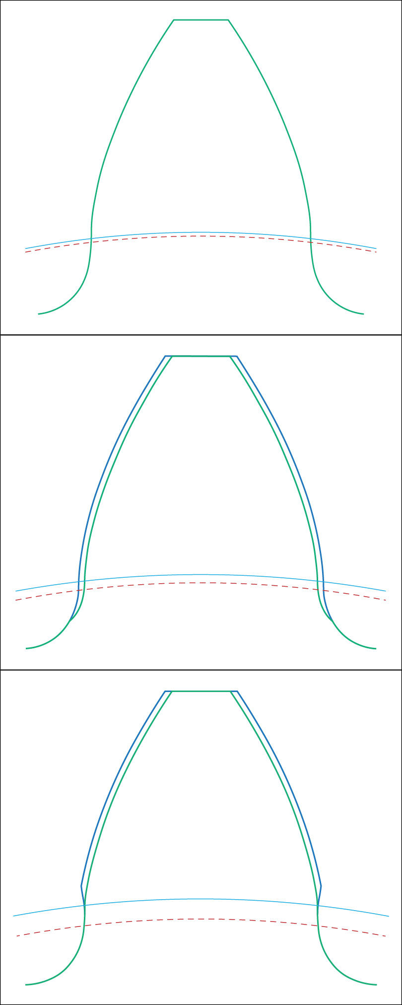
The root form diameter can be generated in three different ways, shown from left to right in Figure 5. The left subfigure shows a tooth generated in a single step without pre-finishing. As the root is generated, the tip of the tool creates the trochoid in the gear’s root area. The point at which the involute and the trochoid intersect defines the root form diameter.
Figure 5—Three different situations that define the root form diameter: Single manufacturing step (top), pre-finishing and grinding (middle), pre-finishing with protuberance tool and grinding (bottom).
The middle subfigure illustrates a process consisting of a pre-finishing hobbing step followed by a grinding step. The grinding disk or worm removes material along the flank down to the root, to a specified diameter determined by the grinding depth. At this point, the generated involute ends, thereby defining the root form diameter. Below this point, a grinding notch is created. Its rounding radius may be significantly smaller than that of the root area itself. This can reduce the tooth’s bending strength because of additional stress concentration and the removal of the highly compressive residual stresses created during heat treatment. To avoid the grinding notch, an artificial undercut can be added. This is produced with a protuberance tool that has a section at the tip with a smaller profile angle. The resulting shape is shown in the right subfigure. The blue tooth profile represents the pre-finishing step with the undercut. The grinding step then removes most of the undercut, and the rounded tip of the grinding disk finishes outside the gear material, while still within the undercut area.
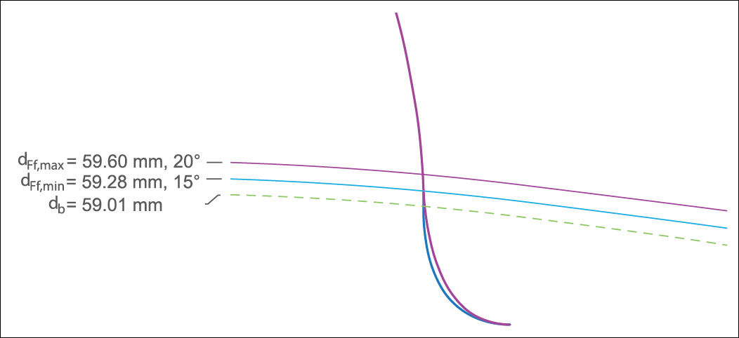
Figure 6—Effect of the short-lead tool on the root area.
If the SAP is smaller than the root form diameter, a short-lead tool may provide a solution. A short-lead tool has a smaller profile angle than the nominal pressure angle of the gear. To generate the same involute while preserving the base circle, the tool module must be adapted so that the tool’s base pitch matches that of the gear. This adjustment results in a different lead, which is why such tools are called short-lead tools. Figure 6 compares the root produced with a 20-degree tool and a 15-degree tool. The red tooth form and pink root-form circle are produced with the 20-degree tool, while the blue tooth form and blue circle correspond to the 15-degree tool. The root of the blue tooth has a significantly smaller rounding radius. This provides more space for the involute to extend closer to the base circle, shown as the green dashed circle, before transitioning into the trochoid. As a result, the blue root-form circle of the 15-degree tool lies below the pink root-form circle of the 20-degree tool. Because the short-lead tool has a smaller rounding radius, the root strength is lower with the 15-degree tool than with the 20-degree tool. This can be compensated for by increasing the hob tip radius, which is feasible due to the smaller profile angle. However, a larger tip radius also increases the root form diameter, so an appropriate compromise must be found.
In summary, rollout graphics are a powerful and precise tool for quickly evaluating the generating process while taking the relevant tolerances into account. They allow designers and manufacturing engineers to visualize the interactions among pre-finishing geometry, stock, and finishing operations, making it easier to evaluate critical parameters such as tip and root form diameters. This type of analysis is normally performed by cutting tool manufacturers, but it can now be integrated directly into the design process. As a result, potential manufacturing issues can be identified and addressed early in the design stage, reducing the risk of costly design iterations during prototyping or production.