[advertisement]
Feature Articles

May 15, 2025

Boris Zhmud


Boris Brodmann


Morteza Najjari


Features

Mechanochemical Surface Finishing for High-Speed Gears for EV Transmissions

Meeting the noise and efficiency demands of the electric drivetrain era

Powertrain electrification has been a growing trend in the automotive industry. Electric motors used in battery electric vehicles (BEVs) operate at high speeds ranging from 3,000 to 16,000 rpm, with high-performance motors reaching over 20,000 rpm. For instance, Tesla’s carbon-sleeved motor used in Tesla Model S Plaid may reach 24,000 rpm at the top speed of 330 km/h. There are experimental designs of interior permanent magnet synchronous motors (IPMSM) reaching 100,000 rpm. The combined inverter/motor efficiency of a typical BEV equipped with a single-speed reduction gearbox reaches a maximum close to the maximum motor speed. Small high-revving motors achieve higher power density and are also lighter and cheaper to manufacture. However, a single-speed gearbox cannot ensure optimum efficiency and driving comfort at different speeds and loads. Hence, quite a few multi-speed gearboxes have hit the market over recent years. Even though the use of a multi-speed gearbox tends to increase the engineering complexity and manufacturing cost of an EV, it is well justified for premium passenger cars, off-road vehicles, and commercial vehicles due to improvements in the driving range, dynamic performance, and gradability (Ref. 1).

Higher speeds of electric motors bring new challenges with lubrication, heat management, and noise. Gear meshing is the primary source of an intrusive whining noise that irritates most drivers. This noise is usually linked to a transmission error and geometric imperfections of the gears. For example, profile angle deviation (fHa) and tooth trace angle deviation (fHb) have been shown to have a significant impact on the noise level through the gearing process (Ref. 2).

Gear microgeometry also has a significant impact on the contact pressure and temperature distribution for meshed gear flanks. Certain modifications, such as crown, taper, and tip relief, have particularly large effects on gear tribology (Ref. 3). Suboptimal microgeometry is associated with an increased risk of scuffing, which is particularly common in transmission gears operating under long-duty cycle hours (Ref. 4).

Gear design usually includes specific optimizations to address issues such as efficiency, noise, and service life. However, it is not always possible to improve all characteristics simultaneously. Perfect gears exist only in theory. In practice, gear manufacturers must always strike a balance between quality and price, which varies a lot from application to application. Gears used in EV transmissions have significant differences in design and, in general, tighter tolerances compared to gears used in traditional stepped and dual-clutch transmissions for ICE-powered cars.

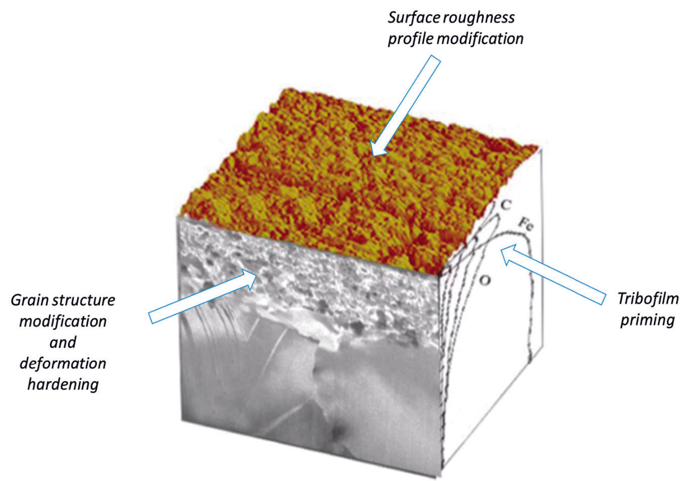
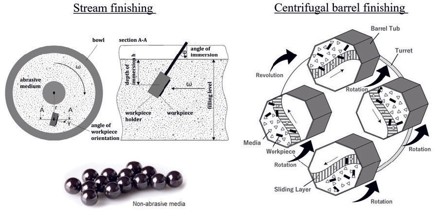
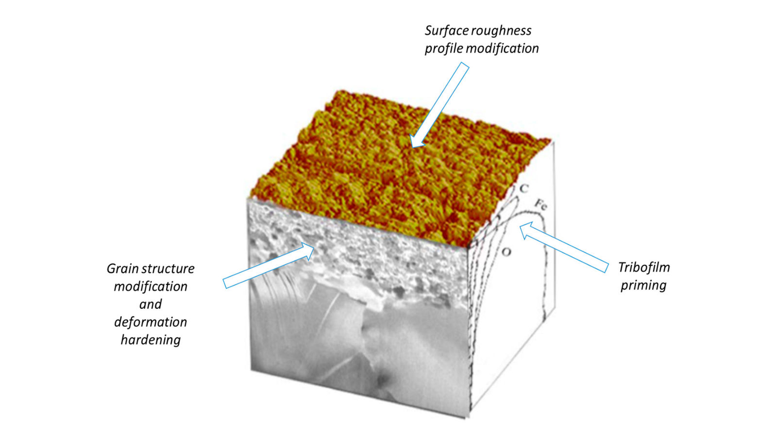
The adequate accuracy for gears used in electric vehicles is around ISO 1328 Grade 6, but high-speed gears rated for speeds over 20,000 rpm may have even higher quality requirements. The contact mechanics in the gear-tooth contact are sensitive to shape deviations at different wavelengths: form, waviness, roughness and microstructure. To optimize the load capacity and the NVH behavior, lead modifications are introduced (Ref. 5). Unfortunately, many traditional gear-cutting techniques, such as generating grinding, profile grinding, gear hobbing, shaving and honing, are plagued by twist errors. To address this problem, special process control or tool geometry adjustment methods have been developed to minimize twist errors in the manufacturing of gears (Ref. 6). To improve transmission efficiency, higher surface quality on tooth flanks is required. This leads to a wider use of advanced surface finishing technologies such as fine grinding or polish grinding (Ref. 7). For instance, with conventional generating grinding, it is challenging to go below Ra 0.5 µm, but when using a combined polish-grinding process, one can reach Ra around 0.1 µm. Mass-finishing processes such as accelerated surface finishing (ASF) and isotropic superfinishing (ISF) allow even smoother surfaces, with Ra down to 0.01 µm. Recently developed mechanochemical surface finishing methods, such as Triboconditioning CG process developed by Tribonex AB, can be used as the final finishing operation bringing about a triad of effects: (i) surface roughness profile optimization, (ii) compressive stress buildup, and (iii) tribofilm priming, which greatly improves the tribological and NVH behavior of gears (Refs. 8,9). Triboconditioning CG treatment can be carried out using standard mass-finishing equipment, such as vibratory tub finishers, centrifugal barrel finishers, and stream- and drag-finishers (see Figures 1–3). The major difference is the use of special chemically reactive process fluids and media types.

Figure 1—The surface effects brought about by the Triboconditioning CG process.


Figure 2—Examples of common mass-finishing platforms suitable for running the Triboconditioning CG process.
Figure 2—Examples of common mass-finishing platforms suitable for running the TriboconditioningCG process.
Share and save:


This article appeared in the May 2025 issue.


Read PDF

[advertisement]


Figure 3—Typical residual stress depth profiles generated by different techniques.
Figure 3—Typical residual stress depth profiles generated bydifferent techniques.

As mentioned, the Triboconditioning CG treatment modifies the surface roughness profile of gears by removing surface peaks and rendering the surface increasingly negatively skewed (Refs. 8,9). This is evidenced by changes in the roughness parameters such as Ra, Rz, Rpk, Rk, and Rsk measured using conventional surface metrology tools such as stylus and white-light profilometry. Unfortunately, the said tools only allow measurements of amplitude roughness. As far as the tribological performance of gears is concerned, having additional information about gradient roughness is expedient (Ref. 10). This can be done by scattered light analysis using an Optosurf OS500 scattered light system. The scattered light method is based on a mirror facet model of the surface (also known as the Kirchhoff or tangent plane approximation) and, hence, is best suited for the analysis of sufficiently smooth and highly reflective surfaces. When the incident light beam hits the surface, the individual light rays are reflected at the microfacets in directions determined by the individual facet’s orientation. As a result, the reflected specular beam broadens. This phenomenon is known as diffuse scattering. The backscattered light is transmitted to a focal plane utilizing Fourier optics. The detected intensity distribution corresponds to the frequency distribution of the scattering angles, as explained in Figure 4.

Figure 4—The principle of gradient roughness characterization using scattered light analysis.

The variance of the angular distribution (Aq) of scattered light relates to the scattering angle (φ) as

where k is a normalization factor, p(φ) is the normalized intensity distribution, n is the total number of angle classes, and the bar denotes the average value. Hence, Aq can be determined directly from the scattered light measurements.

There is a reasonably good correlation between the Aq  parameter and the magnitude of friction losses in the boundary and mixed lubrication regimes, making scattered light measurements highly valuable for gear surface finish quality control (see Figures 5 and 6).

Figure 5—Correlation between the Aq parameter and friction losses (Ref. 10).


Figure 6—Aq maps for tooth flanks for conventionally ground (GR, the top) and mechanochemically finished (MC, the bottom) gears obtained using the Optosurf technique.

The influence of gear microgeometry on various dynamic aspects of gear performance, such as noise generation, contact patterns, contact shocks, and torque variations, can be simulated using various loaded tooth contact analysis (LTCA) models (Ref. 11). LTCA can be further integrated with thermal elastohydrodynamic (TEHD) simulations to study the effects of surface finish and lubricant characteristics on gear tribology at the component level, and CFD simulations to accommodate the macroscopic effects of lubricant flow and heat transfer at the system level (Ref. 12). Figures 7 and 8 show an example of how the surface finish characteristics affect the contact stress map and friction torque for a helical gear pair (Ref. 9).

Figure 7—The effect of gear surface finish on the calculated contact stress map for meshedgears (Ref. 9).


Figure 8—Calculated friction torque for a pair of helical gears shown in Figure 7. The gears are assumed to be lubricated by Dextron VI ATF fluid at 60°C.

The main transmission losses in a vehicle include losses in gears, bearings, seals, and other components. The losses associated with gears and bearings can be further divided into load-dependent friction losses and load-independent viscous losses. A number of robust loss map-based simulation models have been developed that allow calculation of losses for individual transmission components for different transmission designs and speed-torque combinations (Ref. 13). To evaluate the efficiency of electric powertrains, the modular simulation model is often used (see Figure 9). The effects of different surface finishes on load-dependent gear friction can be determined using thermal elastohydrodynamic simulations (see Figure 7) or appropriate component rig tests, such as the FZG efficiency tests (Ref. 9). Then, by using loss map-based simulations, the impact of different surface finishes on total transmission losses can be predicted (see Figure 9).

Figure 9—The principle of loss map-based simulations (Ref. 13).

The average electric car consumes around 200 Wh/km to complete the WLTP* cycle (23 km). The average energy loss in the transmission is around 10 Wh/km, of which load-dependent gear losses are around 50 percent. Hence, while no significant range extension is expected from using mechanochemically finished gears, the reduction in gear friction helps reduce transmission fluid temperature, thus extending the longevity of the fluid and seals. Besides that, mechanochemically finished gears are less prone to wear and micropitting (Refs. 8,9).

Editors’ note: *The Worldwide Harmonised Light vehicles Test Procedure (WLTP) is a global driving cycle standard for determining the levels of pollutants, CO2 emission standards and fuel consumption of automobiles.
Figure 10—The effect of gear surface finishes on the total transmission energy loss in the WLTP cycle.
Figure 10—The effect of gear surface finishes on the total transmissionenergy loss in the WLTP cycle.
[advertisement]

These results show that mechanochemical surface finishing is a promising technology for enhancing the tribological performance of EV transmission gears. It should be noted that a reduction in the surface roughness does not automatically lead to a reduction in the friction torque, as there is an intimate interplay between the gear microgeometry and the surface roughness, and with mass-finishing techniques, it is virtually impossible to modify the surface roughness without incurring some subtle modifications to the microgeometry. In some situations, a rougher surface may be more forgiving of geometric imperfections as it undergoes faster run-in wear, allowing easier tooth profile self-adaptation. From a practical viewpoint, one should strive to manufacture gears either as close as possible to their run-in condition or in a condition that responds well to the running-in. Hence, surface and microgeometry optimizations must always go hand in hand. This is a complex, multidimensional task that requires robust CAE tools, manufacturing and quality control methods, and extensive testing.

tribonex.com

References

  1. F. A. Machado, P. J. Kollmeyer, D. G. Barroso, A. Emadi, Multi-Speed Gearboxes for Battery Electric Vehicles: Current Status and Future Trends, IEEE Open Journal of Vehicular Technology, Vol. 2 (2021), p. 419.
  2. N. Pascalau, I. Vuscan, N. Panc, Research on Influence of Gear Parameters on Noise, Vibration and Harshness Conditions for Automatic Transmissions Run-off Cycle, MATEC Web of Conferences, Vol. 137 (2017), p. 03010.
  3. U. Kissling, Layout of the Gear Micro Geometry, Gear Solutions, September 2015, p. 51.
  4. V. Ganti, Y. Dewangan, S. Arvariya, S. Madhavan, Influence of Micro-Geometry on Gear Scuffing, SAE Technical Paper 2015-26-0187, 2015.
  5. S. Li, A. Kahraman, A Scuffing Model for Spur Gear Contacts. Mech. Mach. Theory, Vol. 156 (2021) 104161.
  6. Hilligardt, V. Schulze, Gear Skiving with Minimum Twist Errors. Forsch Ingenieurwes, Vol. 87 (2023), p. 997.
  7. J. Thalau, P. Geilert, High-End Surfaces of Gears for Electromobility, Gear Solutions, October 2024, p. 36.
  8. L. Everlid, M. Bengtsson, M. Najjari, F. Reinle, A. Storz, B. Zhmud, Improving the Tribological and NHV Behavior of Gears by Mechanochemical Surface Finishing. In Proceedings of the VDI International Conference on Gears, Garching, Germany, 12–14 September 2022.
  9. B. Zhmud, M. Najjari, B. Brodmann, The Effects of the Lubricant Properties and Surface Finish Characteristics on the Tribology of High-Speed Gears for EV Transmissions, Lubricants, Vol. 12 (2024), p. 112.
  10. B. Brodmann, H. Bodschwinna, Scattered light measurement on worm gears with high efficiency requirements. Proc. Int. Conf. on Gears, VDI Verlag, 2019, p. 1567.
  11. M. Molaie, G. Iarriccio, F. Pellicano, F.S. Samani, A. Zippo, Loaded tooth contact analysis and dynamic investigation of Spiral Bevel, Newsletter EnginSoft Year 18 No 4.
  12. B. Zhmud, M. Merelli, Modern Tools for Tribological Optimization of EV Transmissions and e-Axles, SAE Technical Paper 2024-24-0013.
  13. J. Hengst, M. Werra, F. Küçükay, Evaluation of Transmission Losses of Various Battery Electric Vehicles. Automot. Innov., Vol. 5 (2022), p. 388.


For business enquires or application reviews, please contact David Chobany, Technology and Sales Director for the Americas:

david.chobany@tribonex.com

Triboconditioning CG process is offered in the USA in partnership with Precision Finishing Inc

www.precisionfinishinginc.com

Please contact Jeffrey Bell:

jeffrey@precisionfinishinginc.com

[advertisement]