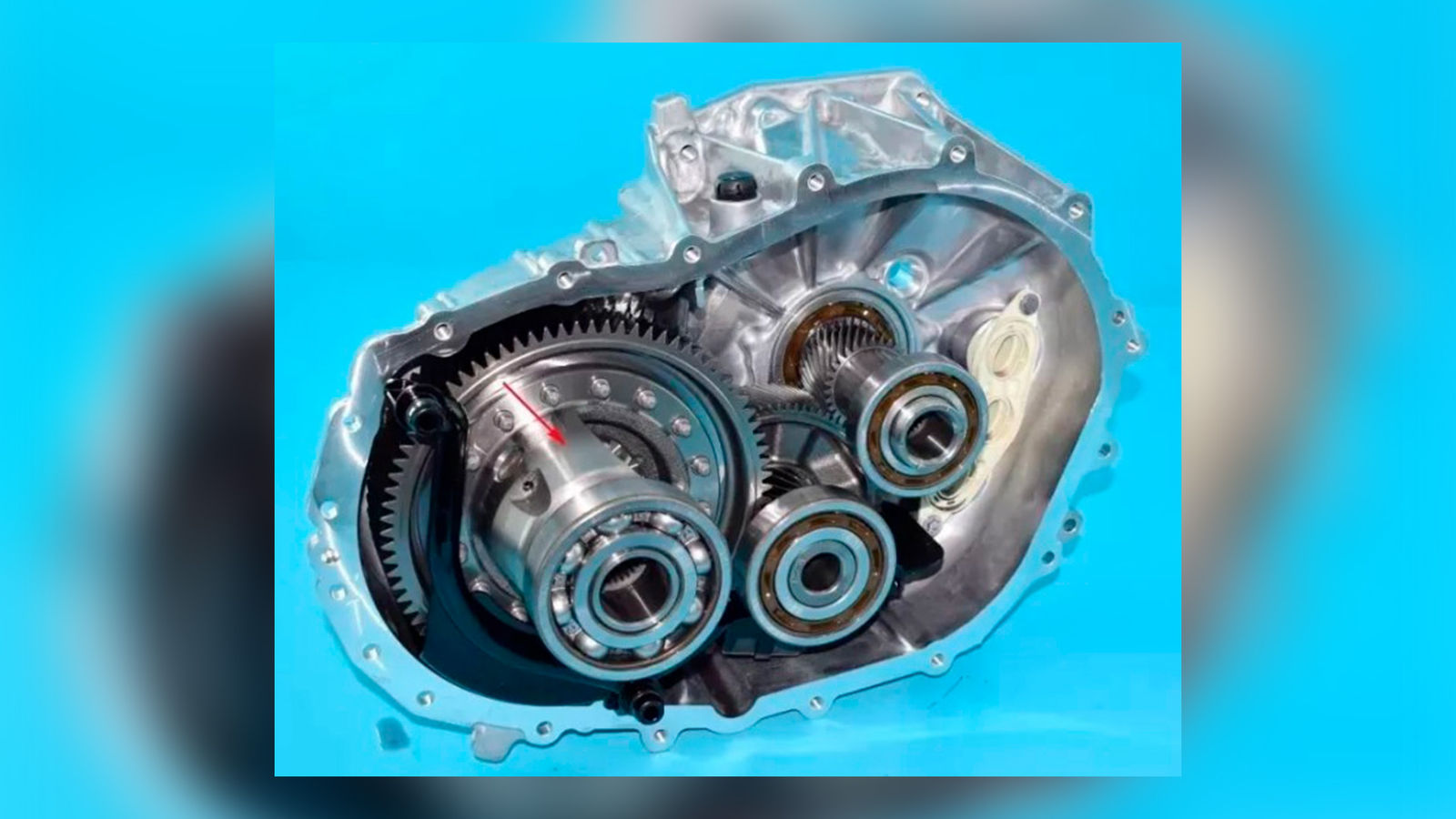
The gear transmission system in an electric vehicle (EV) differs significantly from that of a conventional gasoline or diesel-powered vehicle. This distinction primarily stems from the unique torque and speed characteristics exhibited by electric motors, as compared to internal combustion engines. In most cases, EVs employ a single-speed, two-stage helical gearbox configuration (see Figure 1).
Although relatively simple in design, the gearbox of an EV must meet several critical performance requirements. These include high load-carrying capacity while maintaining a compact and lightweight structure, as well as ensuring high operational efficiency and optimal noise, vibration, and harshness (NVH) performance. The study referenced in Ref. 2 provides an in-depth analysis of these specific requirements and the distinguishing features of EV transmission systems. This study focuses on reducing the size and weight of gears utilized in EVs.
Optimizing the geometry of gear teeth is essential for enhancing the technical performance of EV gearboxes. EV gearboxes typically operate unidirectionally, experiencing high torque and prolonged operation during forward driving. In contrast, during reverse motion, deceleration, and power recuperation phases, the torque levels are significantly lower, and the duration of operation is shorter. These distinct operating conditions involve opposite flanks of the gear teeth, thereby enabling the full benefits of an optimized asymmetric gear tooth design to be realized.
The primary design objective of asymmetric tooth gears is to enhance the performance of the drive flanks under heavy loading, while permitting a degree of compromise on the coast flanks, which are subjected to less frequent and lighter loads. The implementation of the Direct Gear Design method for asymmetric gears enables comprehensive optimization of tooth geometry. This approach results in a significant improvement in power transmission density, maximized load capacity, and a reduction in both the size and weight of the gearbox—advancements that exceed the performance limits of conventional symmetric tooth gears currently used in automotive applications.
Asymmetric Gear Design Approach
Modern gear design standards do not account for the geometry of asymmetric-tooth gears. Consequently, a conventional symmetric gear design is commonly applied to asymmetric gears featuring different pressure angles on their opposing tooth flanks. This methodology employs a customized asymmetric basic or generating rack to define the tooth geometry. Although technically practical, this approach restricts the full potential benefits that asymmetric gears can offer.
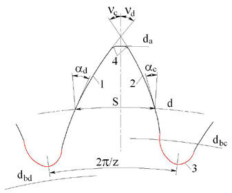
An alternative design approach for asymmetric gears eliminates the reliance on a basic or generating rack in defining gear tooth geometry. The Direct Gear Design method determines the asymmetric gear tooth profile by employing the drive and coast involute flanks derived from two different base circles, separated by the tooth thickness at the reference diameter. Additionally, a tooth tip circle prevents a pointed tooth tip. The optimized tooth root profile aims to minimize bending stress while preventing interference with the mating gear’s tooth tip.
Figure 2—Asymmetric gear tooth profile; 1—drive tooth flank, 2—coast tooth flank, 3—tooth root profile, da—tooth tip circle diameter, d—reference circle diameter, S—tooth thickness at the reference diameter, dbd and dbc—drive and coast flank base circle diameters, υd and υc—drive and coast flank involute intersection angles, αd and αc—drive and coast flank profile angles at the reference diameter, z—number of teeth.
The gear tooth asymmetry factor K is
(1)
The tooth thickness S at the reference diameter d is
(2)
where inv(x)=tan(x)-x—involute function of angle x (in radians).
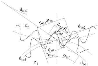
The asymmetric gear mesh is shown in Figure 3.
The drive and coast operating pressure angles are defined by Equations 1 and 3
(3)
The transverse drive and coast contact ratios are
[advertisement]
(4)
(5)
Ref. 3 provides a detailed description of the definition of asymmetric tooth gear geometry.
Figure 3—Asymmetric gear mesh; 1, 2—indexes for the pinion and gear, αwd and αwc—drive and coast operating pressure angles, pbd and pbs—drive and coast base diameter pitches, εad and εac—transverse drive and coast contact ratios.
Asymmetric Gear Tooth Optimization
Asymmetric tooth gears are not standardized, which enables the optimization of virtually any combination of gear tooth geometry parameters. However, the specific optimization goals are determined by the intended application and the performance priorities of the gear drive system. In high-performance applications, such as automotive gearboxes, minimizing stress at the gear tooth root becomes a critical design objective.
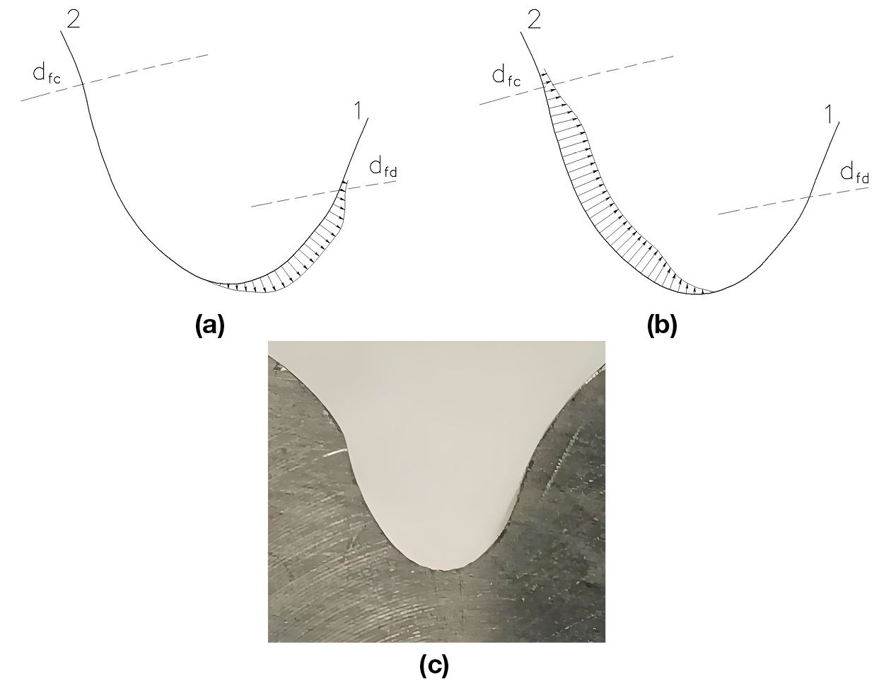
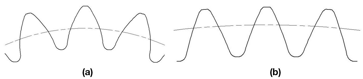
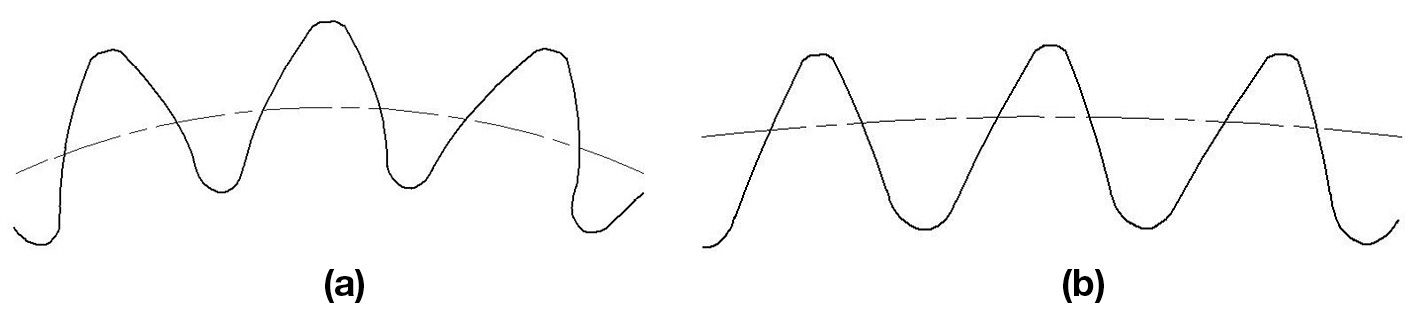
The Direct Gear Design methodology incorporates a tooth root optimization approach developed by Dr. Yuriy Shekhtman. This technique employs two-dimensional finite element analysis (FEA) using linear triangular elements for stress calculations. It is integrated with a random search algorithm to facilitate multiparametric iterations throughout the optimization process. The method utilizes trigonometric, polynomial, and exponential functions to accurately define the optimized root profile. As demonstrated in Figure 4, asymmetric tooth root optimization results in a uniform distribution of tensile and compressive bending stresses along the root profile, leading to a significant reduction in peak root stress values (Ref. 3).
Figure 4—Asymmetric tooth root profile optimization; (a) and (b)—tensile and compressive root bending stress charts along the optimized root profile; 1—drive involute flank, 2—coast involute flank; (c)—photo of optimized tooth root profile.
Comparison of Symmetric and Asymmetric Gears for EV Gearbox
Table 1 presents a comparative analysis between the 2nd symmetric tooth gear stage of a two-stage EV gearbox and its optimized asymmetric tooth version. The objective is to assess the potential advantages associated with the implementation of asymmetric tooth gears.
For the purpose of initial comparison, both the symmetric and asymmetric gear stages maintain the following identical dimensions and parameters:
Number of teeth
Center distances
Hand of helices
Gear face widths
Gear materials
Maximum torque and related rpm
Tooth shape (Design method)
Symmetric (Traditional)
Asymmetric (Direct Gear Design)
Gear
driving
driven
driving
driven
Number of teeth
24
83
24
83
Normal module, mm
2.380
2.382*
Normal drive pressure angle
22°
28°
Normal coast pressure angle
22°
18°
Helix angle
18°
18.015°*
Center distance, mm
134
134
Hand of helix
Left
Right
Left
Right
Profile shift coefficient
0.3102
-0.2608
N/A
N/A
Reference diameter (RD), mm
60.060
207.706
60.112**
207.888**
Drive base diameter, mm
55.278
191.171
52.468
181.453
Coast base diameter, mm
55.278
191.171
56.884
196.723
Tooth tip diameter, mm
66.839
212.498
66.714
212.784
Normal tooth tip thickness, mm
1.08
1.36
0.92
0.83
Tooth tip chamfer, mm
0.30 x 45°
0.30 x 45°
0.20 x 0.20
0.20 x 0.20
Root diameter, mm
54.042
199.701
54.168
200.238
Face width, mm
47.0
45.0
47.0
45.0
Normal tooth thickness at RD, mm
4.253
3.155
4.290***
3.029***
Drive transverse contact ratio
1.56
1.48
Coast transverse contact ratio
1.56
1.86
Overlap ratio
1.86
1.86
Table 1—The geometric parameters of the symmetric and asymmetric gears.
The symmetric gear stage was designed using conventional methods in accordance with established standards, whereas the proposed asymmetric gear stage was developed employing the Direct Gear Design methodology. Due to the differences in design approaches, the normal moduli and helix angles of the symmetric and asymmetric gears exhibit slight variations.
The asymmetric gear stage has an increased drive pressure angle, which is intended to increase the load-carrying capacity of the drive tooth flanks. The coast pressure angle is reduced with the aim of increasing the contact ratio on the drive flank. To achieve the same objective, tooth tip thicknesses are minimized to the allowable lower limit for carburized gears, ranging from 0.3 to 0.4 times of the module value (Ref. 4).
Figs. 5 and 6 show the symmetric and asymmetric gear tooth profiles. Fig. 7 demonstrates the experimental symmetric and asymmetric gears.
Table 2 presents the results of the stress analysis, demonstrating a significant reduction in tooth root stress for asymmetric gears. This improvement is achieved through an increase in tooth root thickness and the optimization of the root profile. Moreover, an increased drive flank pressure angle, along with an increased contact ratio, contributes to lower drive flank contact stress. Additionally, the increased coast flank contact ratio leads to a modest decrease in coast flank contact stress in asymmetric gear designs.
Tooth shape (Design method)
Symmetric (Traditional)
Asymmetric (Direct Gear Design)
Gear
driving
driven
driving
driven
Number of teeth
24
83
24
83
Center distance, mm
134
134
Material
AISI 8620H
AISI 8620H
AISI 8620H
AISI 8620H
Stress Analysis Results (Drive Flanks)
Max. torque, Nm
1306
4518
1306
4518
RPM @ max. torque
2105
609
2105
609
Bending stress, MPa
928
1002
740 (-20.3%)
773 (-26.8%)
Contact stress, MPa
1632
1514 (-7.2%)
Stress Analysis Results (Coast Flanks)
Max. torque, Nm
523
1809
523
1809
RPM @ max. torque
2105
609
2105
609
Bending stress, MPa
415
448
292 (-29.6%)
319 (-28.8%)
Contact stress, MPa
1033
1008 (-2.4%)
Table 2—The stress analysis results.
The maximum contact stress is a primary factor in determining the size of a gear stage. Compared to symmetric tooth gears, optimized asymmetric tooth gears enable a reduction in gear stage dimensions while maintaining equivalent drive flank contact stress levels under identical drive flank loading conditions.
Tables 3 and 4 provide a comparison between the symmetric gear stage and the reduced-size asymmetric tooth gear stage. The modified dimensions and parameters are highlighted in blue.
Tooth shape (Design method)
Symmetric (Traditional)
Asymmetric (Direct Gear Design)
Gear
driving
driven
driving
driven
Number of teeth
24
83
24
83
Normal module, mm
2.380
2.222*
Normal drive pressure angle
22°
28°
Normal coast pressure angle
22°
18°
Helix angle
18°
18.015°*
Center distance, mm
134
125
Hand of helix
Left
Right
Left
Right
Profile shift coefficient
0.3102
-0.2608
N/A
N/A
Reference diameter (RD), mm
60.060
207.706
56.073**
193.917**
Drive base diameter, mm
55.278
191.171
48.943
169.261
Coast base diameter, mm
55.278
191.171
53.061
183.503
Tooth tip diameter, mm
66.839
212.498
62.231
198.467
Normal tooth tip thickness, mm
1.08
1.36
0.86
0.78
Tooth tip chamfer, mm
0.30 x 45°
0.30 x 45°
0.20 x 0.20
0.20 x 0.20
Root diameter, mm
54.042
199.701
50.555
186.791
Face width, mm
47.0
45.0
47.0
45.0
Normal tooth thickness at RD, mm
4.253
3.155
3.996***
2.820***
Drive transverse contact ratio
1.56
1.47
Coast transverse contact ratio
1.56
1.84
Overlap ratio
1.86
1.99
*Normal module and helix angle of asymmetric gears are at operating pitch diameters.
**Reference diameters of asymmetric gears are equal to operating pitch diameters.
***Normal tooth thicknesses of asymmetric gears are at operating pitch diameters.
Table 3—Outlined here are the reductions in center distance, module, and other critical dimensions, as well as minor deviations in the drive and coast contact ratios and the overlap ratio of the asymmetric gear stage. Importantly, the normal drive and coast pressure angles, helix angle, tooth tip chamfers, and face widths of the asymmetric gears remain constant.
Tooth shape (Design method)
Symmetric (Traditional)
Asymmetric (Direct Gear Design)
Gear
driving
driven
driving
driven
Number of teeth
24
83
24
83
Center distance, mm
134
125
Material
AISI 8620H
AISI 8620H
AISI 8620H
AISI 8620H
Stress Analysis Results (Drive Flanks)
Max. torque, Nm
1306
4518
1306
4518
RPM @ max. torque
2105
609
2105
609
Bending stress, MPa
928
1002
841 (-9.4%)
866 (-13.6%)
Contact stress, MPa
1632
1629 (-0.2%)
Stress Analysis Results (Coast Flanks)
Max. torque, Nm
523
1809
523
1809
RPM @ max. torque
2105
609
2105
609
Bending stress, MPa
415
448
334 (-21.9%)
349 (-22.1%)
Contact stress, MPa
1033
1083 (+5.0%)
Table 4—This confirms that the drive flank contact stresses of both the symmetric and asymmetric gear stages are nearly identical. Furthermore, the root bending stresses of the reduced-size asymmetric gears are significantly lower compared to those of the symmetric gears. The observed 5 percent increase in coast flank contact stress is considered acceptable, as it remains substantially below the drive flank contact stress levels.
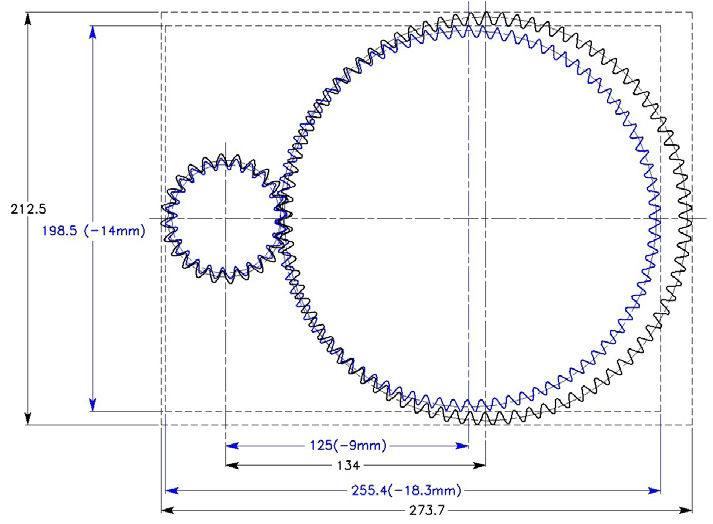
Fig. 8 shows an overlay of the original symmetric and reduced-size asymmetric gear stages, demonstrating a substantial reduction of the asymmetric gear stage cross-section.
Figure 8—Overlay of symmetric (black) and reduced asymmetric (blue) gear stages.
The dimensional reduction of the asymmetric tooth gear stage, as demonstrated in Table 3 and Figure 8, facilitates an assessment of the potential weight savings achievable through the application of asymmetric gears. The size reduction of asymmetric gears is characterized by their transverse cross-sectional profile, while maintaining identical face widths compared to symmetric gears. Consequently, gear weight can be approximated as proportional to the transverse cross-sectional areas of both symmetric and asymmetric gears, as illustrated in Figure 8.
Tooth shape (Design method)
Symmetric (Traditional)
Asymmetric (Direct Gear Design)
Gear
driving
driven
driving
driven
Number of teeth
24
83
24
83
Center distance, mm
134
125
Material
AISI 8620H
AISI 8620H
AISI 8620H
AISI 8620H
Face width, mm
47.0
45.0
47.0
45.0
Transverse cross section area*, mm2
2900
33382
2536
29071
Gear weight, kg
1.77
4.02
1.55 (-12.4%)
3.50 (12.9%)
*defined from the gear model transverse cross sections.
Table 5—This provides a comparison of the weight of symmetric and asymmetric gears.
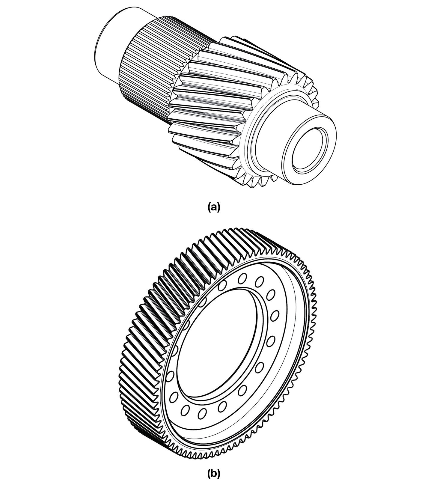
Gear weight is primarily determined by its structural design, which typically includes a central bore and machined relief areas aimed at weight reduction, as well as specific features that support integration with other gearbox components. Figure 9 presents common configurations for gear body design.
Figure 9—Typical driving (a) and driven (b) gear body designs.
Summary
Operating modes of EV gearboxes support the implementation of asymmetric tooth gears.
A comparative analysis between the conventionally designed symmetric gear stage and the optimized asymmetric gear stage, evaluated at the same center distance, demonstrates a significant reduction in tooth stress for asymmetric gears.
This stress reduction enables a notable size reduction of 7 percent in the asymmetric gear stage relative to the symmetric counterpart.
An evaluation of gear weight shows a potential reduction of approximately 13 percent for the asymmetric gear stage compared to the symmetric gear stage.
The study validates the capability of asymmetric gears to improve the performance of EV gearbox systems.
References
Tesla Model 3 electric drive. https://www.sohu.com/a/346284584_413748
Stadtfeld, H. J., “Introduction to Electric Vehicle Transmissions,” Gear Technology, September-October 2020, pp. 42–50.
Kapelevich, A. L., Asymmetric Gearing, Boca Raton, FL: CRC Press, 2018, 287 p.
Rakhit, A.K., “Heat Treatment of Gears: A Practical Guide for Engineers,” ASM International, 2000, p. 209.