The following chapter is from Gear Technology Solutions (The Gleason Works, 2025) by Dr. Hermann J. Stadtfeld. This is the third of four excerpts provided to Gear Technology readers to preview the book’s insights into bevel gear theory, design, and manufacturing.
Dimension Sheet Analysis of Root Fillet
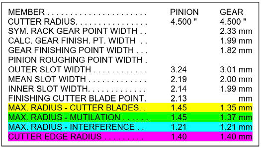
On the first page of the Gleason Dimension Sheet for bevel gears, the section below “Cutter Radius” shows the outer, mean, and inner slot widths. The finishing cutter blade point is a number, which is smaller than the smallest slot width. In Figure 1, the finishing cutter blade point is 10 microns below the inner slot width of the pinion. This is not the top width of the cutting blade for the first flank or the top width of the cutting blade for the second flank, but the distance between the two opposite blade tip corners (if they are superimposed). The top width of the individual blades in praxis is chosen to be 85 percent of the point width. With Coniflex Plus cutters, the first and second flanks are cut with the same blades (Ref. 1).
Figure 1—Maximal limit blade edge radii.
The yellow line in Figure 1 marks the maximal radius the cutter blades can accommodate. The green line shows the maximum cutting-edge radius possible before mutilation occurs. The blue line tells that edge radii larger than the numbers printed will cause interference. The last line highlighted in purple shows the effectively chosen blade edge radius. As a rule of good practice, the blade edge radius should be smaller than the lowest of the highlighted line above. In Figure 1, the chosen blade edge radii are too large.
The effects and rules regarding mutilation, interference, and maximal cutter blade radius are not only applicable to straight bevel gears but equally valid for spiral bevel and hypoid gears. The Gleason GEMS software calculates the maximum recommended radii precisely; however, some exceptions can be made based on the analysis of the Dimension Sheet data by a gear engineer. For example, tip relief, or Toprem, allows for slightly larger than recommended radii.
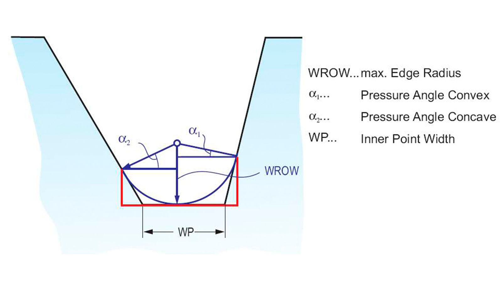
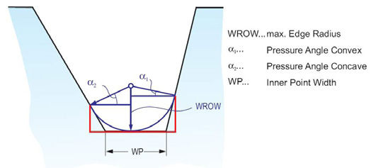
Figure 2—Maximal blade edge radius for a fully rounded root.
Maximal Cutter Blade Radius
The first highlighted line in Figure 1 shows the maximal cutting-edge radius the outside and inside blade can have to machine a fully rounded root. This is the maximal radius that can be used without the risk of a “Gothic arc” blade tip and root bottom. The condition of using the maximal possible radii that fill out the entire root with a theoretically perfect blend with the flank surfaces is visualized in Figure 2 and can be calculated as follows:
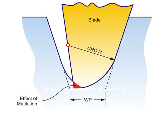
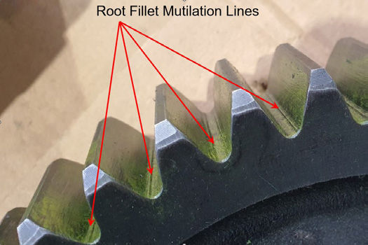
Mutilation happens if the clearance side of a blade leaves a scratch or even a notch in the opposite flank, which is not cleaned up when the opposite flank is generated. The cause of mutilation is an oversized blade top width and/or a sharp corner on the clearance side blade tip, as shown in Figure 3. The mutilation effect in Figure 3 will slide higher up into the flank surface while generating the profile.
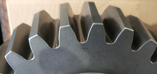
The mutilation lines in Figure 4 are typical for straight bevel gears machined with two tool generators. The blade segments that are used in two tool generators always have sharp corners on the clearance side tip. It is recommended to use blades with a small overlap in the center of the root. However, manufacturers like to use the same blade segments for a variety of different designs that have the same pressure angle.
Figure 4—Mutilation lines.
This often leads to a large blade top width overlapping up to the point where the clearance edge cuts scratches or ridges in the opposite flanks. The mutilation lines are found in and above the root fillet.
Coniflex cutting with interlocking solid cutters on older cradle-style machines also leads to the same problem. These cutters always have sharp clearance side tip corners without any radius. Trying to use the same cutter for a certain job variety often exceeds the point where the top width of the cutter blades is equal to the point width (equal slot bottom width).
Mutilation commonly does not lead to interference because the mutilation lines or scratches represent a stock off condition. However, if these scratches are within the flank surface working profile, then a sliding of the opposite member topland corner across the scratches might be possible and would result in a certain mesh disturbance.
Interference Limit
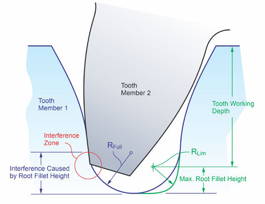
Interference occurs when a disturbing step is at or above the transition between the root fillet and the flank surface. If the blade cutting edge radius, according to Figure 1, is larger than the maximum recommended value, then the most common interference is created.
[advertisement]
If a root fillet transition is inside the active working depth, as shown with the blue profile in Figure 5, then an interference zone has been created. The green drawn fillet radius in Figure 5 indicates the maximal acceptable radius, which has its transition to the flank surface below the working depth.
Figure 5—The interference phenomenon.
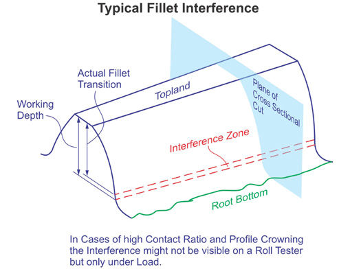
The location and extension of the interference zone is depicted in Figure 6. Before any damage is visible in the interference zone, it is typical to detect noise on a roll tester and to obtain a larger motion error than expected. Often, interference cannot be detected visually after rolling the gear set on a tester. In this case, a single flank test might show larger-than-expected errors. A fast Fourier transformation (FFT) of the single flank results will show a first harmonic amplitude that is larger than the motion error amplitude from the design calculation.
Figure 6—Critical interference zone.
At the interference limit, when no interference can be detected in a roll test, only small deflections or assembly tolerances will make the interference audible, and after some rolling, also visible.
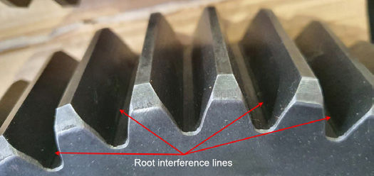
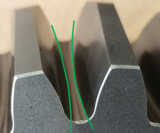
Visible interference lines of a straight bevel gear that has been cut on a two-tool generator are shown in Figure 7. These lines are within the interference zone. Below the interference lines, steps are visible mainly on the right side of the root fillet transition. The steps indicate that the cutting depth of the two blades in a two-tool generator had been adjusted differently. The left side blade was adjusted deeper and formed the right-side root fillet. The right-side blade started with its root fillet radius about 0.5 mm higher and was not able to form its root fillet radius all the way to the deepest root line.
Figure 7—Visible root interference lines and steps.
It appears as if the interference lines at the right-side flanks are within the starting fillet radius, which the right-side blade could not finish because it was not adjusted deep enough. This blade and machine setup error caused the typical interference as shown in Figure 5.
The Consequences of Interference
It appears that straight bevel gears, manufactured with two-tool generators as shown in Figures 4 and 7, have been designed with their blade edge radii at or above the interference limit. Although the root fillet looks cleaner with the larger blue fillet radius in Figure 5 and suggests higher bending strength, the reality is different.
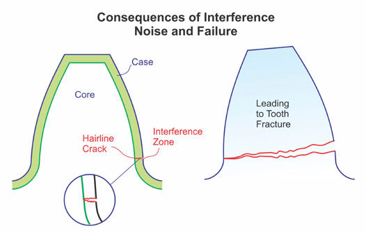
The result of an interference is often failure after many service hours of a straight bevel gear transmission. Some small interferences can polish out and “heal themselves” during the first 20 to 100 hours of service. If the interference is more severe, the first scratches within the upper area of the root fillet become visible after a break-in of the gear set. During some fraction of the calculated lifetime of the gear set, the scratches will initiate the population of hair cracks in the case depth, most commonly in profile direction. Over time, the load cycles make the hair cracks grow, which results in some cases in tooth fracture (see Figure 8).
Figure 8—Tooth fracture initiated by interference.
What looks like a smooth and fully rounded root radius can reduce the strength and lead to a catastrophic failure if the chosen radius is larger than the interference limit radius.
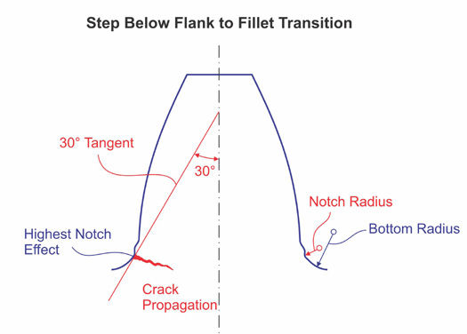
The root fillet step problem, which was discussed in connection with Figure 7, is investigated further with Figure 9. Figure 9 shows a profile that is very similar to the real profile in Figure 7. If the 30-degree tangent to the root fillet is drawn into the profile, then the tangent point is at or close to the point with the highest notch effect. The 30-degree tangent has been proven in numerous finite element calculations and in the analysis of real-world fractures to be the point with the highest risk of a tooth fracture.
Figure 9—Tooth fracture initiated by steps below the root transition.
This means that imperfections in the root fillet transition, as shown in Figures 7 and 9, can cause tooth fracture if the gear set is used in a power transmission. A fracture, as shown in Figure 9, is independent of an interference problem. However, because interferences and root transition steps have been observed together on the same gears or pinions, it should alert gear engineers when root transition steps are recognized. Steps and fins at the bottom of the root are rather harmless. They are far enough away from the 30-degree tangent and are merely an aesthetic disturbance.
Straight Bevel Gears with Coniflex Plus
For common designs with a face width that is equal to or smaller than 26 percent of the cutter radius, the root width is the smallest at the toe and the largest at the heel. In case of larger face widths (smaller cutter radius), the root width between toe and heel has an hourglass shape, like in the photo in Figure 10. This makes the root width the smallest at midface, which is why the maximal blade edge radii in the Dimension Sheet are calculated, in this case, based on the midface slot width.
Figure 10—Fully rounded root at midface.Figure 11—Hourglass root width provides a dam effect.
The straight bevel gear in Figure 10 has a fully rounded root at the center of the face width with small gables at the toe and heel. The flanks are generated below the working depth without the potential of interference. This condition is superior to the flank and root appearance in Figures 4 and 7 of the same gear designs but cut with two-tool generators.
Strength Advantages due to Hourglass Effect
The hourglass effect in the root of straight bevel gears cut with Coniflex Plus cutters provides the shape of a dam. The dam effect is one of the reasons why the convex side of spiral bevel ring gears is preferred as the side with the major load (drive side).
The dam effect increases the root bending strength, which is proven with FEM calculations and field tests with spiral bevel and hypoid gears.
Blade Radii Optimization
Figure 12—Lost working areas drawn in gear tooth projection.
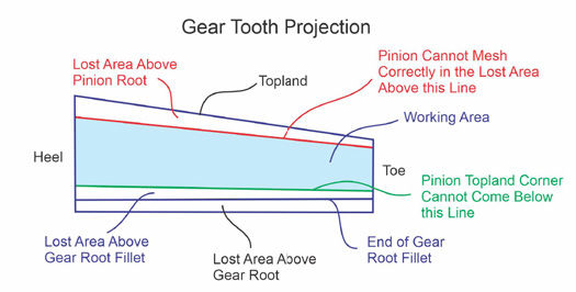
For straight bevel gears, more than for spiral bevel gears, the criteria of kinematic undercut exist. The projected tooth in Figure 12 shows a gear tooth with the active working area drawn in blue. Both the lost area above the pinion root and the lost area above the gear root should be avoided. First, the question of the nature of the lost area must be answered. Possible causes are:
Edge radius too large—causes interference
Kinematic undercut—causes possible interference
Physical undercut—weakens teeth but causes no interference
The lost areas in Figure 12 indicate the three fundamentally different mesh deficiencies, listed above. The first lost area between the topland of the gear and the red border line exists because the gear topland corner will not mesh above the red line. The second lost area between the end of the gear root fillet and the green line exists because the pinion topland corner will not mesh below the green line. In both cases of lost area, either the edge radius of the blades is too large, or a kinematic undercut or physical undercut exists.
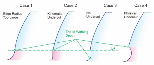
A distinction between physical undercut, kinematic undercut, or interference due to an oversized blade edge radius is difficult in the design stage. The graphics in Figure 13 propose a procedure that reveals the reason for a lost dedendum (root) area. If the edge radius is too large, then it limits the working depth (case 1). When the edge radius in the calculation is changed to a small value, for example, 0.1 mm, and the lost area in Figure 12 stays the same, then a kinematic undercut exists (case 2). If the end of the working depth drops down and matches the end of the gear root fillet in Figure 12, then the blade edge radius was too large, or the clearance is too small (case 3). An increase in the lost area after reducing the edge radius reveals a physical undercut (case 4) (Ref. 2).
Figure 13—Lost working area.
Reducing or eliminating kinematic or physical undercut can be achieved with an increased pressure angle or a larger profile shift. However, restrictions regarding pressure angle or profile shift exist because both reduce the topland thickness and the root width.
Figure 14—Final choice of edge radii and clearance.
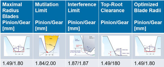
To come to a final choice of suitable blade-edge radii, the Table in Figure 14 was created. Basically, it follows the recommendations from the Dimension Sheet. The smallest radius of the three limit radii in the Dimension Sheet should be selected:
Maximal Radius Cutter Blades
Maximal Radius Mutilation
Maximal Radius Interference
An important additional criterion is the top root clearance, which should have the same value as the blade edge radius. Because the maximal permissible edge radii are mostly different for pinion and gear, the Coniflex Pro software has separate input values for pinion and gear clearance. If the clearance is lower than the edge radius, an interference will occur, although the edge radius is below the interference limit. The clearance amount should not be below the maximal root fillet height shown in Figure 5, which is approximately equal to the blade edge radius.
In some cases, for strength reasons, or because the same cutter should be used across a variety of different job designs, the edge radius must be larger than recommended in the Dimension Sheet and in Figure 14. The solution to this conflict is to apply top relief on the teeth of the pinion and gear. Top relief can be realized by a simple topland chamfering or by applying a kinematic top relief. The kinematic top relief for Coniflex Pro is integrated in the generating cycle and requires no additional machining time.
Summary
Root interference is a common problem not only for straight bevel gears but also for cylindrical gears, as well as for spiral bevel and hypoid gears. Interferences are often difficult to detect, but their influence on the performance of a gear set is significant. Interference lines and increased single-flank errors are, in many cases, only present if deflections under load are applied. Even the smallest interference leads to noisy operation and often causes flank surface damage or tooth fracture.
The Gleason Dimension Sheet shows what the maximally permissible blade edge radii are. The gear engineer who designs a new bevel gear set should select the smallest value of the three different limit radii for the cutter edge radius. In addition, attention has to be paid to the top-root clearance. If this value is too small, then an interference will still occur, although the blade edge radii have been chosen correctly.
References
Stadtfeld, H.J. “Gleason Bevel Gear Technology—The Science of Gear Engineering and Modern Methods for Angular Transmissions,” Company Publication, The Gleason Works, Rochester, New York, 2014, ISBN 978-0-615-96492-8, Pages 235–239.
Stadtfeld, H.J. “Practical Gear Engineering—Answers to common Gear Manufacturing Questions,” Company Publication, The Gleason Works, Rochester, New York, 2019, ISBN 978-0-578-46376-6, Pages: 107–116.