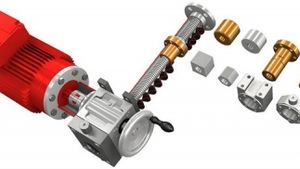
I’m building a custom gearbox with 7075 T-6 spur gears, and I’m concerned
that aluminum flakes will enter the races on the roller bearings (SKF 2307) and cause premature failure. So my question is — should I place an oil seal on the shaft first to protect the bearing — or is this an unfounded concern and I should mount the seal in the typical manner outside the bearing? Or both? Or go with a sealed bearing? I’m confused and could use your expertise, please.
PUBLISHER'S PAGE | 2015-12-01 | From Power Transmission Engineering
Sometimes I feel like I blink and another year is gone. By the time most of you read this, it will be at or near the end of 2015. If you’re like us, you’ll be reflecting on the past year and looking forward to the next.
One of the great benefits of Gear Expo for us here at Gear Technology is the opportunity to meet faceto-face with many of the people who, in one way
or another, contribute to our success throughout the year. After all, our success is dependent almost entirely
on information and the people who provide it. These contributors
include researchers at top technical universities, the heads of technology at major gear industry corporations, independent consultants with decades of gear industry experience, members
and volunteers at leading industry organizations like the AGMA,
our technical editors and others.
Reducing losses and increasing profits by instituting a motor management plan is what this series of articles is all about. Here in Part I, we discuss how to create a motor inventory and establish repair-or-replace motor guidelines. Subsequent topics in this
three-part series will address (Part II)
motor failure policies and purchasing
specifications, and (Part III) repair
specifications and preventive and predictive maintenance, respectively.
PUBLISHER'S PAGE | 2015-10-01 | From Power Transmission Engineering
This issue we take a long, hard look at motor efficiency, and you should, too. After all, electric motors used in industrial settings are the single largest consumer of electricity in the United States. Upgrading your electric motors is not only good for the environment, but it’s
also good for your bottom line. Sure, saving electricity lessens
the burden on our country’s energy infrastructure. But it
also saves you money in the long run.
If only there were some source of endless knowledge, experience
and wisdom to guide you through your gear-related problems.
If only there were some philosopher on a mountaintop
whose sole purpose was to bring enlightenment to your gear noise problems, to unravel the mysteries of profile shift, to provide insight to a critical gear manufacturing problem or to explain the meaning of life (gear life, that is).
Gear Expo 2015 takes place October 20–22 in Detroit. If you haven’t already made plans to attend the show, you might be might be missing out on a great chance to learn more about gears, find new potential suppliers and network with your peers.
FEATURE ARTICLES | 2015-09-01 | From Power Transmission Engineering
Is there a gear software package out there that will calculate the design of spur, helical, worm, and planetary gearsets? Also, we would like a program that calculates stresses and material selection. Finally, we would like to have the program calculate bearings loads, too. Thank you for your help.
rotary-type blowers? Examples: for motor KW; RPM; temperature; pressure production; lifetime; etc.
In other words, how do I choose between belts or couplings?
We are currently experiencing wear on the bull gear on our
converter at the steel plant.
We want to be able to draw the original gear profile to compare
this with the worn tooth before we decide on the next steps.
I have attempted this, but there is a correction factor given and I
am unsure how to apply this. Could someone give advice on this?
Please find attached the PDF’s for the bull gear and the pinion gear.
They are old drawings! The wear is on the wheel.
If you haven’t already done so, you should make plans to attend Gear Expo in September. It’s a unique and important show, and you should take advantage of it.
Since we began publishing in 1984, Gear Technology's mission has been to educate our readers. For 31 years, we've shown you the basics of gear manufacturing as well as the cutting edge. We take our educational mission quite seriously, and we go through steps that most publishers don't have time for or wouldn't consider.