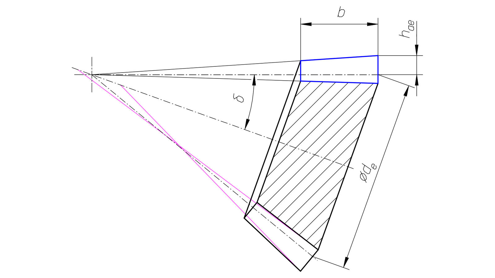
Figure 1—Macrogeometry of a bevel gear—axial section.
Introduction
Bevel gears fall into two categories: the non-offset bevel gears (including straight bevel gears and spiral bevel gears) and the hypoid gears. An idealized non-offset bevel gear pair can be visualized as two cones rolling on each other without sliding. These cones are commonly referred to as pitch cones, and their angles can be calculated based on explicit relationships to the gear ratio and the shaft angle (Ref. 1).
In the case of hypoid gears (i.e., bevel gears with hypoid offset), the two rolling cones are replaced with one sheet hyperboloids. In the axial sections of the gears, these hyperboloids are represented as curves, which are usually simplified to straight lines, and so cones are created, which are again referred to as pitch cones. Due to the nature of hyperboloids, an infinite number of hyperboloid configurations exist for each hypoid gear set; therefore, additional criteria need to be applied to select a specific configuration. These criteria include checking the limit radius of curvature of the tooth trace (Ref. 1) and optimizing the contact ratio (Ref. 2). Consequently, the pitch cones can only be calculated iteratively, and they depend not only on gear ratio and shaft angle (as in the case of non-offset bevel gears), but also on hypoid offset, tool radius and other factors (Ref. 1). Considerations on an actual face cutter having different radii on its internal and external sides and at different profile heights, on a tilted face cutter having local radius of curvature dependent on further parameters, and on contact ratio being derived from tooth contact analysis lead to the conclusion that when pitch cones are calculated this way, they are dependent on specific gear cutting technology, tooling and microgeometry modifications. Therefore, a method for calculating pitch cones in hypoid gears based on macrogeometry parameters similar to that used in the case of non-offset gears is sought after in this paper.
Symmetries
A spiral bevel gear set from Ref. 3—Method 0 is taken as an example. To calculate the pinion’s pitch cone angle δ1 we need to know the shaft angle Σ and the numbers of teeth z1 and z2.
For the gear:
We refer to these as intrinsic pitch cones because they are derived solely from the gear set’s macrogeometry, independent of manufacturing tooling or technology-dependent parameters. Gear sizing includes choosing the pinion’s outer pitch diameter de1=63.5 mm, the face width b=25.4 mm, and the pinion’s outer addendum height hae1=6.281 mm. The dedendum height is used for illustration and can be set arbitrary. With these parameters, it is now possible to draw the pinion as shown in Figure 1.
The pitch cone, the face cone and the root cone share the same apex. The face cone and the root cone often get technology-related modifications, an example of which is indicated here with pink. A corresponding basic planar crown gear, based on the unmodified macrogeometry, is drawn blue. The addendum height is directly proportional to the cone distance.
The visualizations starting with Figure 2 show translucent crown gear bodies, so it is possible to see their alignment with the corresponding gears. They were created in POV-Ray software, which is capable of calculating objects and their interactions in a mathematically exact way (Refs. 4, 5). The pinion’s face cone and the corresponding crown gear’s cone in Figure 2 are tangent to each other, and they make contact along a straight line; the same applies to gears in Figure 3. The interactions of curvatures on the back cones actually indicate the locations of theoretical pitch diameters.
Figure 3—Spiral bevel gear and its crown gear.
Some of the bevel gear manufacturing methods use non-planar crown gears (with pitch cone angle ≠ 90 degrees) (Ref. 1), or with that angle being effectively varied in the gear cutting process by modifying the roll motion. In the case of non-offset bevel gears that does not change the resulting pitch cones.
When hypoid offset is applied to a spiral bevel gear set, a difference in spiral angles of the mating members is created, while they still share an operating normal pitch. Since the transverse pitch is related to the normal pitch in a non-linear way incorporating the cosine of the spiral angle and the pitch diameter is directly proportional to the transverse pitch, the pitch diameter and angle are affected by changes of the spiral angle also in a non-linear way. Therefore, the spiral angle β must be evaluated in gear sizing and included in the initial hypoid data specification, so it can be used in the calculation of the pitch cones.
A sample hypoid gear set from Ref. 3—Method 1 is taken as an example.
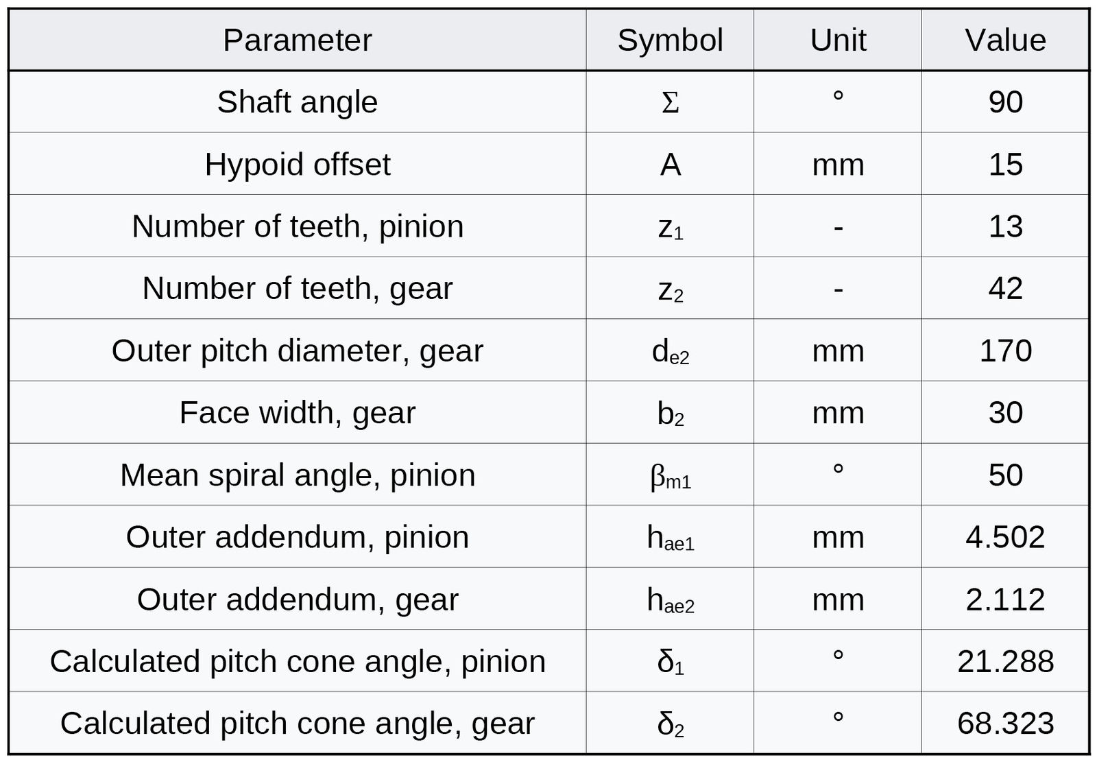
Table 1—Hypoid gear parameters—Method 1.
Figures 4 and 5 reveal that in this case the face cones do not line up with the corresponding crown gear cones. The iterative pitch cone calculating procedure in this example loops until the lengthwise tooth mean radius of curvature limit is met (Ref. 3). However, the proprietary spiral bevel and hypoid gear calculation software developed at Oktoida (Ref. 6) is capable of taking the cone line-up condition into account. To do that, the crown gear axial positions of points of interaction between the face cones and the crown gear cones at the inner and outer cone distance are matched using the modified Newton’s method. It is not surprising that in this way it is possible to select a pitch cone that allows for meeting the cone line-up condition for one of the members. Calculations showed that for each hypoid gear set one special pitch cone pair could be found with which that condition is satisfied for both members. A gear set based on these special pitch cones exhibits the symmetries found in non-offset bevel gears. Their calculation is based on macrogeometry parameters without necessity to reach out for any other prerequisites, like, e.g., for technology-related cutter radius. Therefore, these special pitch cones will be referred to as the intrinsic pitch cones. In this example, they were calculated δ1=20.239 degrees and δ2=69.389 degrees.
Figure 4—Hypoid pinion and its crown gear—Method 1.Figure 5—Hypoid gear and its crown gear—Method 1.
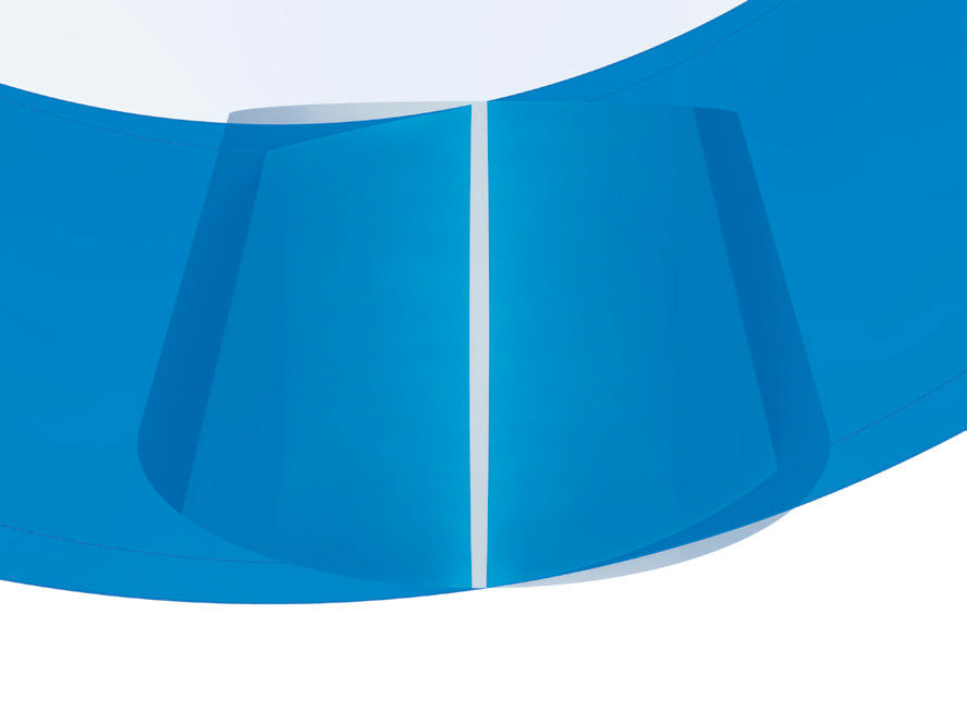
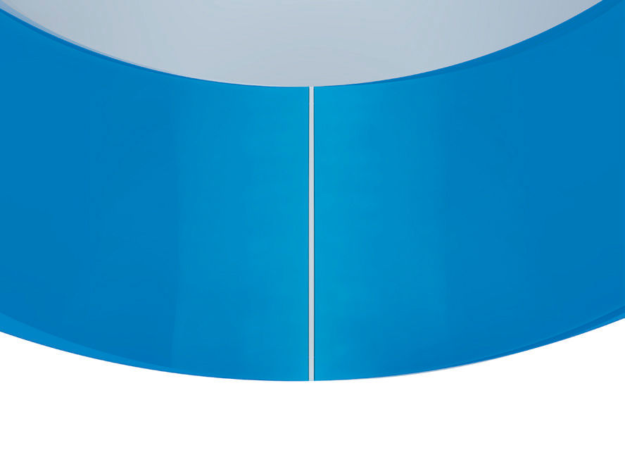
Examination of Figures 6–9 reveals that the cones intersect along a curve and that the edges on both ends of the cones concur with that curve. Therefore, the cones are situated in a one-and-only arrangement, and any movement of one in relation to the other would diverge the intersections. The only degree of freedom left is a rotation around an axis passing through the points of intersection on both ends. However, any additional rotation of such would alter the offset and the mounting distances.
Figure 6—Hypoid pinion and its crown gear—Method 1 with the intrinsic pitch cone.Figure 7—Hypoid gear and its crown gear—Method 1 with the intrinsic pitch cone.Figure 8—Hypoid pinion and its crown gear—Method 1 with the intrinsic pitch cone—view from above.Figure 9—Hypoid gear and its crown gear—Method 1 with the intrinsic pitch cone—view from above.
The cones are not tangent to each other as in the case of non-offset bevel gears; instead, they intersect at a small angle. As a result, a thin contact line (Figures 2–3) is replaced with a stripe (Figures 6–9). In this example, those cone interaction stripes are located left from the curve of intersection of the cones. No information about such a phenomenon has been found in the literature.
The cone interaction stripes tend to be wider in the middle of their length, which can be best seen in Figure 8. This is explained by the aforementioned simplification of hyperboloid shapes by replacing them with cones. As the cone angles get bigger, the cones tend to differ less from the corresponding hyperboloid shapes; therefore, the cone interaction stripes get more uniform in width (Figures 7 and 9).
In Figure 8, the pinion axis is positioned right in relation to the crown gear center; therefore, the back cone of the pinion protrudes out of the crown gear also on the right side. The gear in Figure 7 is also set off to the right. However, when the gear set is brought to its operational arrangement, one of the members will be turned upside down to face the other member. Then, both the member offsets will add up to the total operational offset in the gear set. In the case of the gear set based on non-intrinsic pitch cones (Figures 4 and 5), the members are set off in opposite directions. Therefore, to achieve the specified operational offset, the pinion must generate an offset bigger than specified, and the gear offset is subtracted from it.
[advertisement]
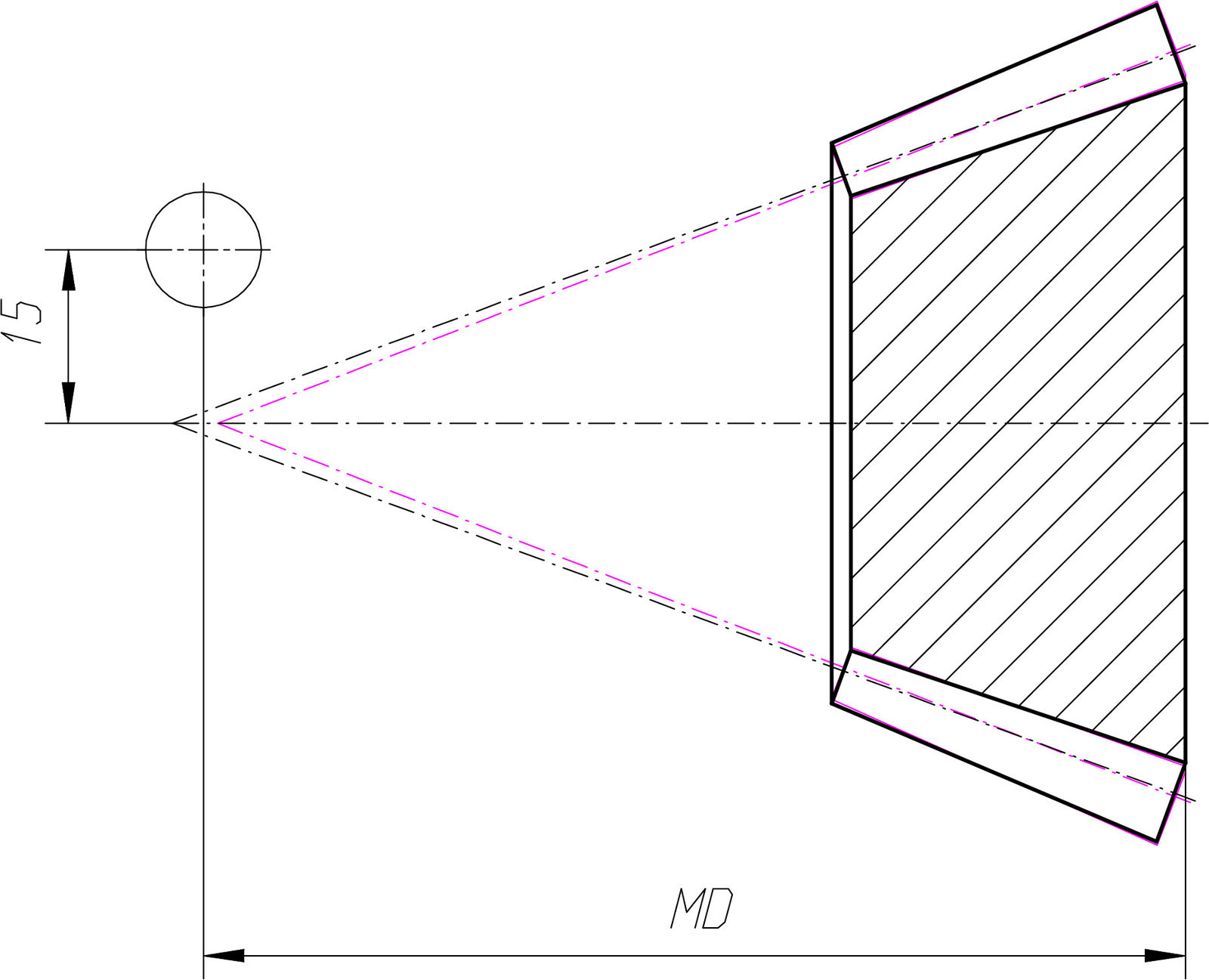
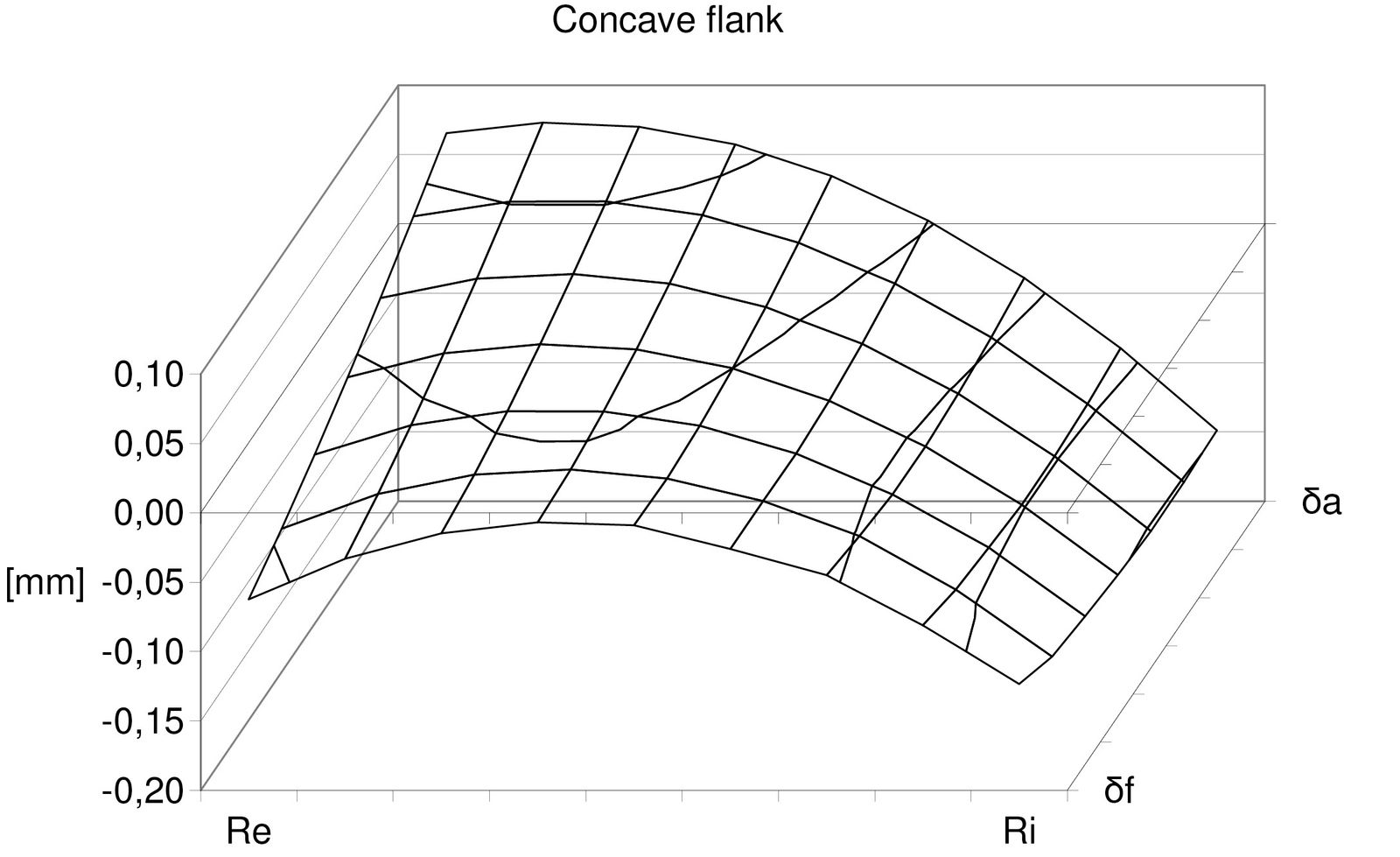
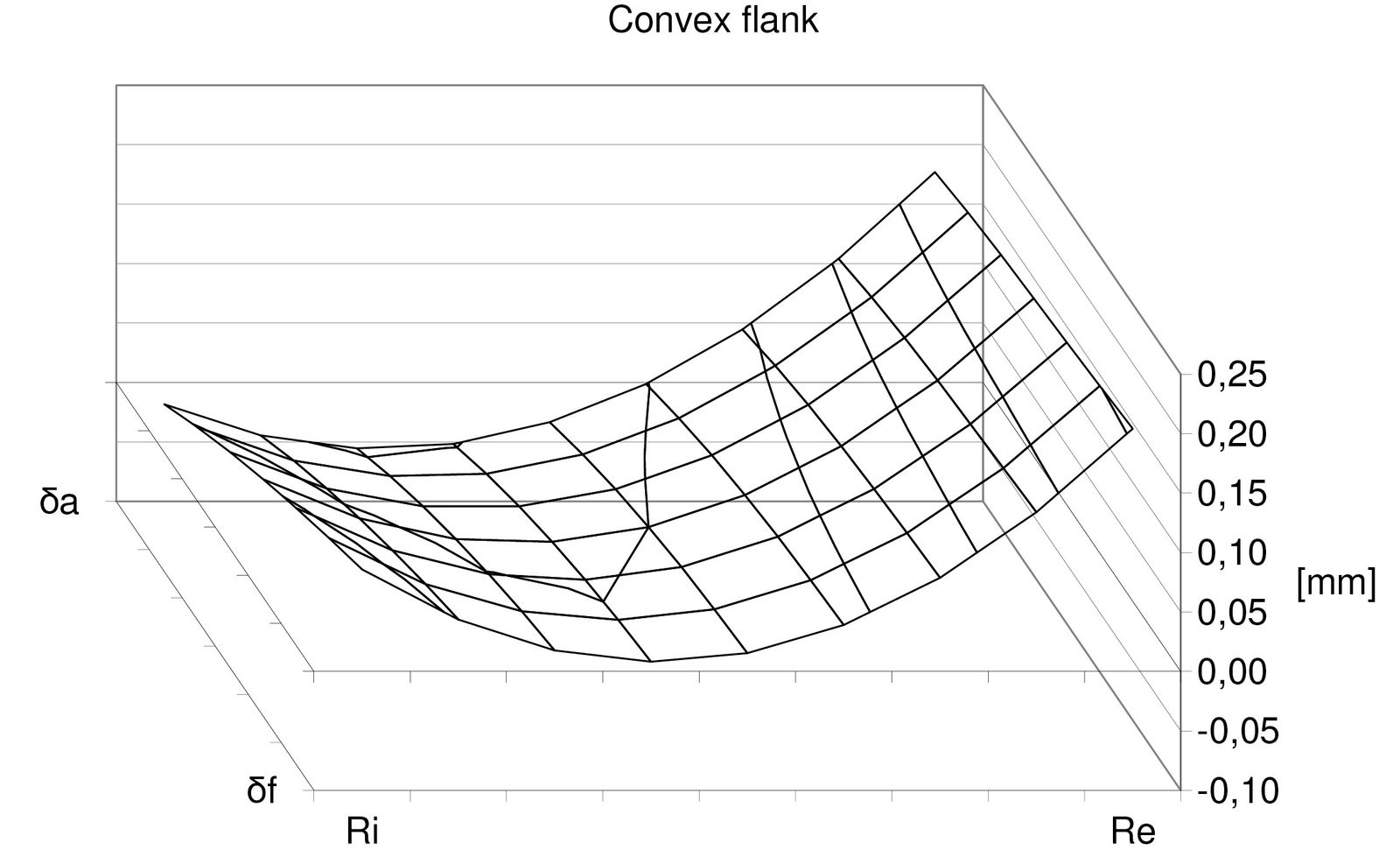
Figure 10 shows an axial section of a hypoid pinion based on data from Table 1 but with the intrinsic pitch cone δ1=20.239 degrees. The original geometry with non-intrinsic pitch cone is drawn in pink. The pinions are positioned in their mounting distance MD; the center of the mating hypoid gear is marked with a circle. The pitch cones intersect in the middle of the face width. To visualize differences between topographies of flanks based on the intrinsic and non-intrinsic pitch cones, Oktoida’s spiral bevel and hypoid gear calculation software was utilized to calculate flank point clouds along with corresponding normal vectors. In that software, clouds and vectors can be calculated in theoretical or technological mode. In the latter case, calculations are based on technology-related parameters, like exact specifications of face milling cutters that will be used to cut the gears or machining kinematics. As such parameters are typically evaluated in a later stage of technology development, the clouds and vectors in this example were calculated in the theoretical mode, and the results were used to create graphs in Figures 11 and 12. The magnitudes of these flank topography differences reveal their potentially significant influence on gear’s operation.
Figure 10—Hypoid pinion—Comparison of the intrinsic and non-intrinsic pitch cone-based geometries—Method 1.Figure 11—Hypoid pinion—Differences between the intrinsic and non-intrinsic pitch cone-based flank topographies—Method 1—Concave flank.Figure 12—Hypoid pinion—Differences between the intrinsic and non-intrinsic pitch cone-based flank topographies—Method 1—Convex flank.
For a basic crown gear deviating from a planar one by 1 degree, the intrinsic pitch cone angles in this example were calculated δ1=20.275 degrees and δ2=69.352 degrees. It indicates that the basic crown gear’s pitch angle has only a minor influence on the resulting intrinsic pitch angle in a gear. Due to the fact that the basic crown gear’s pitch angle is a technology-related parameter that might remain undefined at the gear macrogeometry design stage, I propose to always use a planar crown gear (with δ0=90 degrees) in calculations of the intrinsic pitch cones.
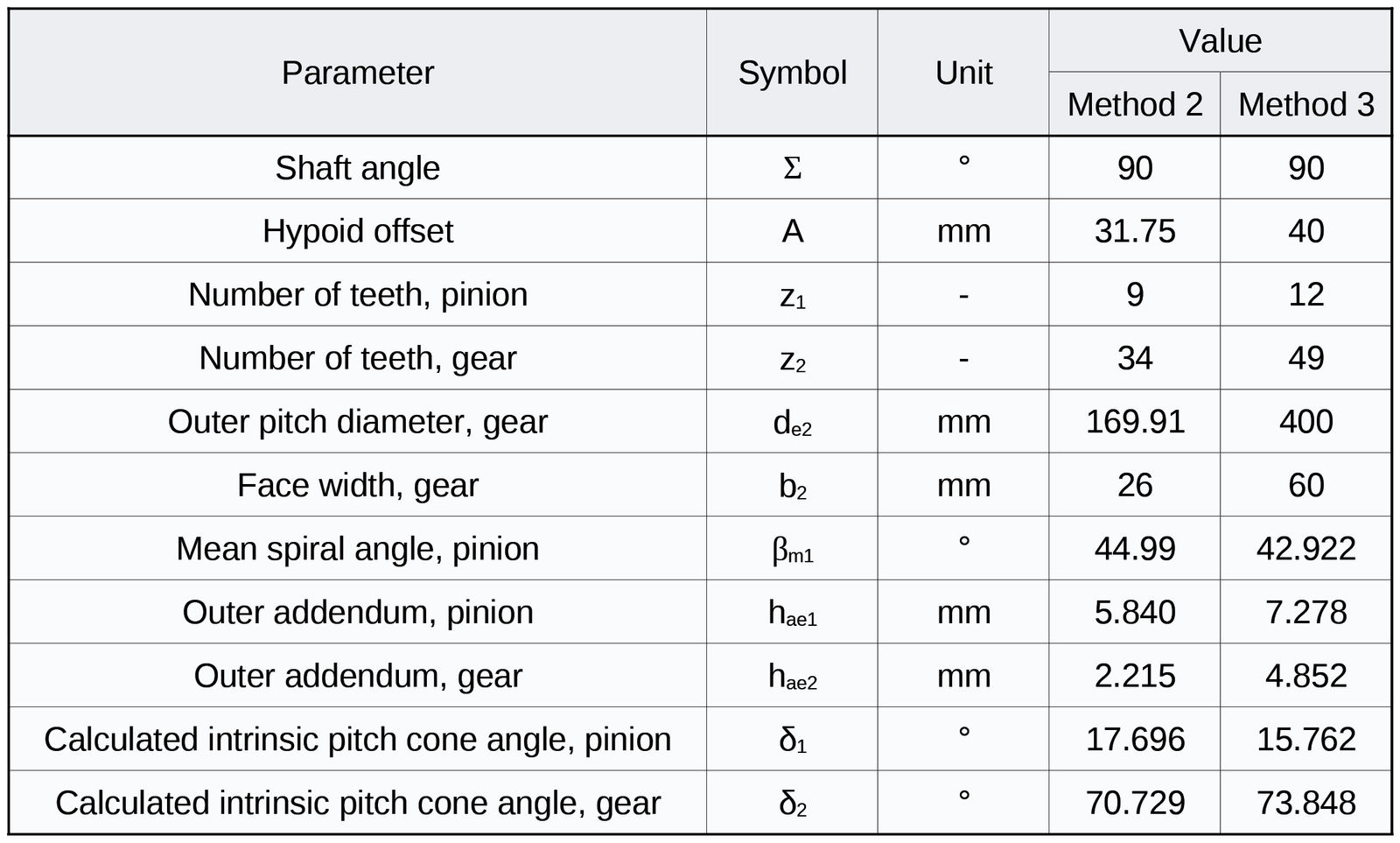
The intrinsic pitch cone angles of two remaining sample hypoid gear sets Method 2 and Method 3 from Ref. 3 were calculated, and the results are shown in Table 2.
Table 2—Two further sample hypoid gear sets from Ref. 3—Input parameters and calculation results.
Conclusion
The pitch cone is one of the fundamental concepts in bevel gear design and manufacture, having considerable influence on gear geometry and operation. In the case of hypoid gears, for each gear set one unique pitch cone configuration can be found that exhibits symmetries similar to those existing in non-offset gears. The calculation of these cones is based on macrogeometry parameters with the spiral angle (or, in the general case, the lead angle) βm additionally included in the input data set. This intrinsic pitch cone concept has been proven in the field, being used by default in the spiral bevel and hypoid gear calculation software that has been utilized in Oktoida for over 15 years.
References
Klingelnberg, J. Editor (2016), Bevel Gear: Fundamentals and Applications, Springer-Verlag Berlin Heidelberg.
Miyamura, H., Shibata, Y., Inagaki, M., and Aoyama, T. (2013), Design Method for Optimizing Contact Ratio of Hypoid Gears, 25th International Conference on Design Theory and Methodology; ASME 2013 Power Transmission and Gearing Conference, Vol. 5.
ISO 23509:2016, Bevel and hypoid gear geometry.
POV-Ray Documentation. Available at: https://www.povray.org/documentation/3.7.0/t2_3.html#t2_3_3_3 (Accessed: 17 March 2025).
POV-Ray Primitives. Available at: https://en.wikipedia.org/wiki/POV-Ray#Primitives (Accessed: 17 March 2025).
Oktoida is a company based in Poland that manufactures gears and gear units.