In the example in Figure 2, the pressure angle changes from about 39° on the outer diameter to around 10° on the inner. This leads to very steep tooth flanks on the internal side, through which the involute becomes very short—and is represented on only a small part of the tooth height—followed by an undercut which further reduces the usable region. On the outer part, the tooth gets a pointed tip. As a result, minimum and maximum diameters are determined, which limit the total possible tooth width of the gear. This represents a distinct difference compared to a bevel gear pair. While bevel gears can transmit a higher torque through a higher tooth width, the face gear pair is limited to the region forming acceptable tooth contact conditions with a spur gear.
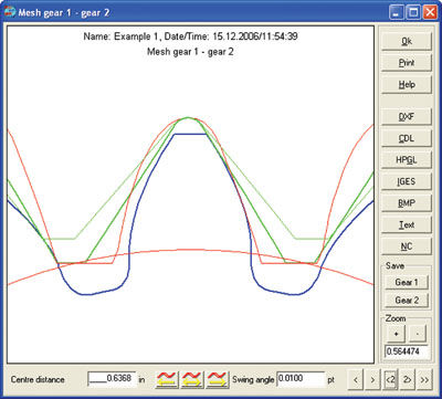
Figure 2—Plot of the pairing of a cylindrical helical with a face gear. Three sections of the face gear are illustrated. Inner: Violet; Middle: Green; Outer: Red.
By clever choice of width offset bv (Figure 3), i.e., through a shift of the tooth width center opposite the reference circle, the maximum permissible tooth width can be optimized.
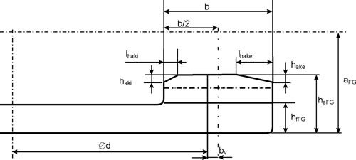
Figure 3—Definition of the tooth offset bv and the addendum change hake/i at the inner and outer diameters.
When sizing a face gear, it makes sense, after fixing a minimum and maximum pressure angle, to next determine the inner and outer diameter. By setting the outer and inner diameter as reference diameter, Equation 1 is redefined for the range of module available.
 (2)
(2)
Beyond considering the raw numbers, it is helpful to also consider a graphical representation of the teeth. With a little experience, the engineer will determine from a 2- or 3-D graph (for example, Figs. 1 or 2) in which direction the significant parameters should be changed in order to reach an optimum solution.
The overwhelming number of applications use straight-toothed face gears. Helical face gears can, with the appropriate design procedure, offer benefits in strength and noise development.
In contrast, the problem emerges that the flanks are no longer symmetric in that the left flank no longer corresponds to the right. In practice, this implies that a possible undercut on a flank appears earlier on one side than on the other. In Figure 2, for example, a distinct undercut can already be seen on the right gear flank at the inner diameter, while on the left flank there is only a very slight undercut. Likewise, the pressure angle in the example is different, being 31.2° (on the middle section) on the left, and 29.5° on the right flank of the tooth.
These differences on the flank have an influence on the strength so that transmissible power is different, depending on the direction of rotation. If only one direction is to be used, then the flank to be used can be optimized without consideration of the opposite flank.
Experience teaches that theoretical geometry considerations, which describe a flank form in terms of the involute function, lines and arcs, always tend to a limit sooner or later. Tried-and-tested, and much safer, are tooth form calculations which are based upon simulation of the meshing process, or, better yet, on a simulation of the machining process. In these simulations, the trajectory of a point on the active surface is traced (Fig. 4) until the speed normal to the surface of the tool is a zero point (Fig. 4). These positions are potential places of contact on the tooth form surface. The actual points of contact must then be determined, removing any so called “imaginary” points whose relative motion satisfies the contact criteria but whose position is actually outside of the material on the gear surface. Attempting to identify the difference between real and imaginary points presents the greatest difficulty to this approach. Apart from the usual standard algorithms for the classification of points in a plane, empirical approaches must be employed which recognize the known properties of the required tooth form in order to achieve a well-defined tooth form with a degree of certainty.
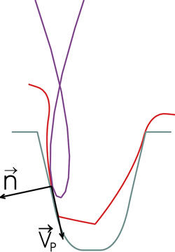
Figure 4—Trajectory (blue) of the surface point of the pinion (red) relative to a face gear surface (green). The position with zero relative speed defines a potential contact point.
The calculation of the 3-D tooth form of the face gear can, on the basis of traditional production methods—meshing with a pinion-like shaping cutter—be defined in this way (Fig. 1). The 3-D body can be output in a variety of graphics formats so that, in any arbitrary CAD system, a form can be constructed in order to manufacture face gears using other production methods such as injection molding, sintering or form forging.
The 2-D representation is well-suited for the checking of undercut or pointed teeth in a face gear. In the previous diagram (Fig. 2), the tooth forms at the inner-, mid-, and outer-gear diameters of the face gear are simultaneously drawn. If the gear is rotated in discrete steps, the meshing conditions at each position can be checked throughout the meshing cycle. In the case of extremely pointed teeth or unacceptable contact ratio, the tooth height can be shortened (Fig. 3), analogous to the approach in hypoid gears.
In order to reduce sensitivity from errors in the axis position or axial distance, crowning can be produced on the tooth flanks. This can be applied relatively easily to face gears produced with a pinion-like shaping cutter (or equivalent milling tool) which has one or two teeth more than the intended pinion. A comparison of the tooth forms shows the influence of the higher tooth number of the cutter on the crowning of the tooth form. For a large-width offset, bv, of the face gear, the crowing can be shifted to one side.
Each transverse section through the spur with the corresponding part of the face gear basically corresponds to a rack and pinion system. Based on the rack theory, it is possible to calculate the pressure angle, contact line and contact ratio in each section (Fig. 5).
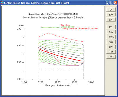
Figure 5—Position of the contact lines on the face gear flanks.
Strength Calculation
Following are various approaches for the strength calculation of the face gear:
1) Development of proprietary calculation methods—for example, a finite element method (FEM) calculation combined with a pressure evaluation.
2) Adjustment of the method for the resistance calculation of spur/helical gearing (e.g., ISO 6336).
3) Adjustment of the method for the resistance calculation of bevel gearing (e.g., ISO 10300).
The first possibility is not practical, in that it is possible to spend years conducting a comprehensive series of measurements. The development of ISO6336, for example, has taken decades to prepare, being founded upon multiple theoretical and practical—by means of test rigs—work programs.
The third method is relatively simple, but leads in the end to ISO 6336. The ISO 10300 calculation method converts the bevel geometry in the first step to an equivalent helical gear, and then derives calculation methods directly from ISO 6336.
This leaves only the second approach—the adjustment to a suitable standard for spur/helical gears (e.g., ISO 6336), to which can be added some of the more similar concepts of the ISO 10300. Critical points to consider in doing this are that the contact
ratio from inner to outer diameter changes to such an extreme that only a calculation based on contact ratio at the mid-diameter is carried out (analogous to bevel gears), or that only the average of the three
calculations at the inner, mid and outer diameters is considered. Furthermore, all the important dimensions of the spur/helical gearing being used are in conjunction with the plane of the reference circle. But in a face gear, the reference circle lies in a plane at right angles to the reference circle of the pinion. Certain formulae must therefore be adjusted to cope with the concept of an infinite radius. This problem is identified by the analysis of rack gearing
Calculation to ISO 6336
The Crown Gears method of calculating the strength of face gears is based upon the spur/helical calculation according to ISO 6336 (Ref. 1). Because of the curvature in the path of contact, there is a raised total contact ratio due to the so-called lead overlap ratio. This is somehow comparable to the overlap ratio in helical gearing in which helical-toothed face gears contain an overlap ratio that is given by the helix angle ß. A virtual helical angle, ßv, can be derived from the curvature of the contact line, with which the effect can be considered using the helix angle factors Yß and Zß. Transverse contact ratio ε&alpha becomes the value used in the middle of the tooth width. The derivation of the face load coefficient KHß and transverse coefficient KHα, according to methods from ISO 6336, cannot be directly implemented for face gears. Again using the Crown Gears calculation, the values are usually set to KHß = 1.5 and KHα = 1.1, so that a similar approach to the calculation of bevels (ISO 10300) is chosen.
Calculation to ISO 10300
As previously mentioned, the use of the strength calculation according to ISO 10300 for bevel gears can be an appropriate alternative. Face gears belong to the class of bevel gears, and can be thought of as a limiting case, with cone angle 0° (pinion) and 90° (face gear). The strength calculation for bevel gears is conducted on the basis of an equivalent spur/helical gear, the spur/helical having the same tooth form as the bevel. In the case of the face gear, this gives the virtual tooth number Z1v = Z1 and Z2v = infinity for the pinion and gear, respectively.
A validation with Crown Gears calculations, and the methods of ISO 6336 or ISO 10300, produces a very good match in that deviation at the root and flank safety factors in all cases is under 10%, with most under 5%. However, because the Crown Gears method is restricted concerning the correct length of the contact lines, the ISO6336 method is recommended.
Load distribution over the tooth width. The load distribution at the root and on the flank can be calculated very accurately by using an FEM analysis. But this requires a comparably large time investment, while a very quick method for the estimation of the Hertzian pressure and root stress is given by performing the calculation in discrete steps as a rack. In doing so, the course of the pressure at the pitch point and the root stress (calculation procedure according to ISO 6336 for racks) can be defined, assuming a constant linear load, across the tooth flank (Fig. 6).
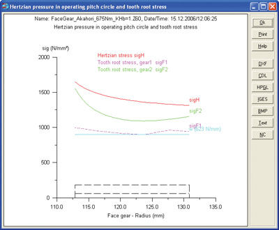
Figure 6—Course of stress curves of a face gear: geometry of the face gear corresponds to the test gear of Akahori (Ref. 2).
Akahori carried out investigations of ground case-hardened face gears (mn=2.75 mm; b=18 mm; bv=5 mm; Z=28:85) (Ref. 2). The tooth root stress, which has been measured via strain gage, provides a good match with the calculated course of tooth root stress for the face gear (Fig. 6). Also, the photo of the tooth flank after 107 load cycles shows a pitting condition, which corresponds well with the region of higher Hertzian pressure on the tooth flank in Figure 6 (Ref. 2).
Theoretical Safety Factors
As with every gear, a validation of the strength is given as safety factors for pitting and root strength. In order to evaluate these factors, it is important to know the minimal required values. This is a general problem associated with machine construction. Minimum safety values can (according to the conditions and requirements) be very different, and should be determined most of all on the basis of experience and proven results from a test rig. In cases where nothing similar is known, the following values can be used as a starting point:
Minimum root safety factor (SFmin): 1.4
Minimum flank safety factor (SHmin): 1.0
Regarding face gears, well-documented results are readily available. During the measurements of Akahori (Ref. 2), a distinct pitting was observed at a driving torque of 675 Nm after 10^7 load cycles. Cracks or breaks in the root did not appear. A validation according to ISO 10300, when using the factors discussed above (KHß = 1.5 and KHa = 1.1), gives factors in Table 1 by calculation. These factors are impressively low. In Akahori’s testing, the gear used was a ground face gear of very high precision. The face load co-efficient chosen in this case was set much too high. A validation through ISO 10300 with factor KHß=1.0 gives a flank safety factor of 1.0, and root safety factor of 0.80. The flank safety factor corresponds roughly to expectation, but the root safety is so low that a break in the root can be expected. Evidently the calculation method is very conservative in this case. Based on the analysis above, where obviously the gear must be hardened, it can be cautiously interpreted that, for industrial applications with face gears made from steel, the root strength is less critical than in spur gears, and presumably the safety factors can in fact be set as follows:
Minimum root safety factor (SFmin): 1.0
Minimum flank safety factor (SHmin): 1.0

Calculation of the scoring safety factor
The calculation of the scoring safety factor is difficult because of the very different sliding velocities, and the changing flank pressure across the tooth flank. In the Crown Gears calculations, no check for scoring is conducted (Ref. 1). On the other hand, Akahori reported massive problems with scoring in the higher sliding speed region (Ref. 2). It is therefore necessary to consider adding similar calculations to detect a scoring problem. As previously described in the stress distribution, a reasonable possibility can be the calculation of the scoring safety factor according to German Institute for Standardization (DIN) 3990 in discrete steps. Figure 7 shows the course of the scoring safety, according to criteria of flash and integral temperature across the tooth flank.
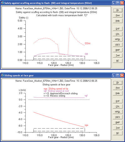
Figure 7 (Top & Bottom)—Scoring pitting safety factor against flash and integral temperature and speed at tip and root. Geometry of the face gear corresponds to the test gear of Akahori (Ref. 2).
In order to arrive at a realistic calculation, all steps should be calculated at the same temperature. In working through the calculations, it can be shown that the factor according to the integral temperature contains many jumps. This occurs if the point E of the contact line is close to the pitch point. The re-calculation of the flank temperature at point E relative to the average flank temperature with the formulae of (DIN) 3990, becomes somewhat imprecise. On this principle, the use of the flash temperature criterion is recommended for face gears.
Summary
The face gear is certainly a challenging component to design, but its use in some applications is significantly more advantageous than an equivalent bevel gear solution. Through the availability of software for sizing face gears and their associated tooling, it is now possible to efficiently overcome special calculation and manufacturing problems associated with tooth forms of this type in arriving at a practical, alternative solution.
References
1. Basstein, G. and A. Sijtstra. “New developments concerning design and manufacturing of face gears.” Antriebstechnik, 32 (1993), Nr.11.
2. Akahori, H., Y. Sato, Y. Nishida, and A. Kubo. “Test of the durability of Face Gears.” Organi di trasmissione, 2002, Nr.12 oder MTP2001-Fukuoka, The JSME Int. Conference, 2001, Japan.
3. Lewicki, D.G., R.F. Handschuh, G.F. Heath, and V. Sheth. “Evaluation of Carbonized Face Gears,” The American Helicopter Society 55th Annual Forum, Montreal, Canada, 1999.
Dr. Stefan Beermann is vice president of KISSsoft AG, having previously served from 1996-1997 as KISSsoft product manager for L. Kissling & Co., AG. His 2000 doctorate thesis was “Simulation of Vibrations in Gearboxes Applying Spectral Simulation.”
Dr.-Ing. Ulrich Kissling is managing director and CEO for KISSsoft AG, the software company he founded in 1998. He was previously managing director of L. Kissling Co. SA, a Swiss gear manufacturer. Kissling is chairman of the gear committee for the Swiss Standards Association and
a voting member for Switzerland in the ISO TC 60 committee. He has also written extensively on calculation procedures for machine design and power transmission, and has conducted numerous seminars, courses and lectures on gear technology.





 (1)
(1)


 (2)
(2)


