Tool Life and Productivity Improvement Through Cutting Parameter Setting and Tool Design in Dry High-Speed Bevel Gear Tooth Cutting
Fritz Klocke and Alexander Klein
Management Summary
The introduction of carbide tools and hard coatings has led to a quantum leap in material removal rates and tool life in manufacturing automotive-sized bevel and hypoid gears, as the tools and coatings have in other areas of machining technology (Refs. 1–6). Further benefits of the new techology are the ability to abandon the use of coolant and the improvement of quality, which partly goes back also to advancements in the machine tool technology and the implementation of quality loops in manufacturing (Ref. 3–4 and 7–13).
However, the number of influential factors on manufacturing cost per piece is high, and an in-depth process analysis and understanding has not yet been established in many areas.
Yet this fundamental knowledge is required to show the right direction for further enhancements of economic efficiency and productivity, since thorough process development is difficult to conduct during and after the start of production in an industrial environment (Ref. 13). Therefore, thorough machining investigations are conducted at WZL within the scope of an AiF research project (13713 N/1) on high speed bevel gear machining.
This article presents some of the findings of cutting investigations at WZL in which the correlation of cutting parameters, cutting materials, tool geometry and tool life have been determined.
Finally, the idea for a new WZL face milling tool concept, which has some significant theoretical advantages over state-of-the-art tool systems, is presented.
Introduction
The value-added chain for bevel and hypoid gears in high-volume production usually contains the technologies which are shown in Figure 1. This article focuses on the soft cutting of teeth. It shall contribute to a deeper understanding of the correlation between the choice of the technological parameters and the consequences on tool life and cost per piece and shall also show some findings and approaches for an increase of manufacturing excellence.
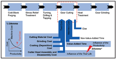
Figure 1—Manufacturing technology chain for high volume bevel gear production.
Before attempting to decrease the cost per piece in bevel gear tooth cutting, it is suggested that an analysis be made of the technological system to be optimized, in order to identify the influential factors, the cost drivers and the possible levers for achieving relevant improvements. Therefore, a number of influence factors on the most important output variables are shown and structured in an Ishikawa chart (see Fig. 2). The manufacturing system can be subdivided into the tool system, the machine tool system (including work holding device), the workpiece and the cutting parameters.
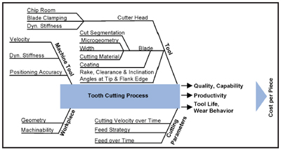
Figure 2—System analysis of bevel gear tooth cutting technology.
The high number of influential factors, their interdependencies with regard to the output variables, and the intransparencies (areas where we lack knowledge) about all of the effects and correlations make the manufacturing system highly complex, according to Wöhe’s definition (Ref. 14). Thus total understanding is nearly impossible. Despite this, the investigations can improve production, since selected parameters have been subjected to planned variations and full-factorial designs while other parameters (e.g. machine tool, workholding devices, workpiece, tool material and batch) have been kept constant to achieve a good signal-to-noise (S/N) ratio in laboratory trials.
Systematic Experimental Studies on Selected Parameters in Bevel Gear Machining and their Effect on Tool Wear Experimental setup and design of experiments. Figure 3 shows the experimental setup for the wear studies at WZL. Instead of using a fully equipped cutter head, the parts are cut with one inside and one ouside blade each. Only this way has it been possible to conduct the amount of trials in the laboratory, since the number of required blanks is reduced by an order of magnitude. The blade wear is monitored over the tool life by measuring the wear land width or chipping size. Furthermore, all blades have been analyzed with a scanning electron microscope after the end of a trial. The end of tool life was defined as a maximum wear land width or chipping size of VBmax = 0.15 mm.
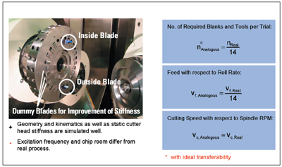
Figure 3—Setup for single blade group experimental trial at WZL.
The presented findings were obtained by manufacturing a face-milling designed SUV ring gear, as shown in Figure 4. All blanks were manufactured in the same batch.
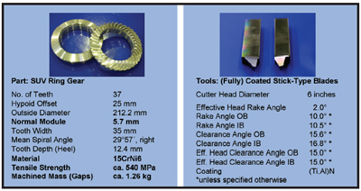
Figure 4—Trial workpiece and tool data.
In most trials, fully coated carbide blades have been applied as specified in Figure 4.
Cutting parameter variation. In Figure 5, the obtained tool lives in an extended full-factorial cutting speed and feed variation are presented. Except the finishing operation trial (fBG = 0.03 mm per blade group), all trials were intended to determine the tool wear behavior at high material removal rates (roughing).
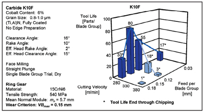
Figure 5—Tool life overview of the global cutting parameter variation.
The results show a significant negative effect of the cutting velocity on the tool life within the chosen set of other parameters. The cutting speed variation (vc = 280; 330; 380 m/min) brings about a left-curved “tool life vs. cutting speed” curve. At very high cutting speeds and/or feeds, the wear mode changes from abrasive wear to small or larger chippings (see also Figs. 6 and 7).
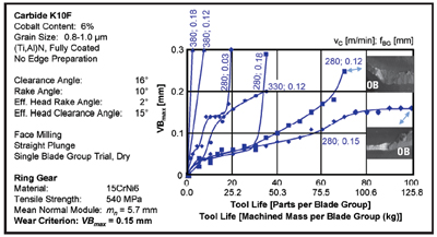
Figure 6—Wear charts of the cutting parameter variation.
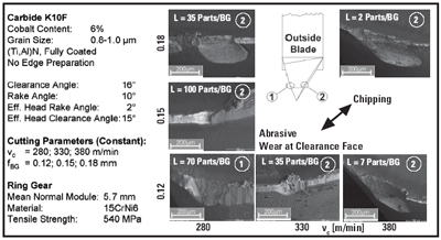
Figure 7—Wear mechanisms of carbide tool K10F.
In the feed variation, a strongly nonlinear behavior of the tool life, which would not have been revealed in the mere full-factorial matrix, was identified in the medium roughing feed trial. The tool life overview in Figure 5 and the wear charts and pictures in Figures 6 and 7 show that there appears to be an optimum feed at about fBG = 0.15 mm (at the applied set of other parameters). It should be mentioned, however, that other effects, which might occur with a fully equipped cutter head (chip jam or dynamic effects) have been intentionally excluded in the single blade group laboratory trial.
The feed variation also shows that beyond tool life optimum feed, increases in feed rate have a negative effect on the tool life. However, the ratio of tool life drop and machining rate enhancements is notably better than the corresponding ratio in the cutting speed uprating.
The finishing feed trial (fBG = 0.03 mm) supports the theory of the existence of only one maximum of the “tool life vs. feed” curve. The obtained tool life at the very low feed is, accordingly, much inferior to the tool life at higher feeds. Obviously, the ratio of load per cut and number of load cycles to machine a given volume of material has an optimum at undeformed chip thicknesses of around 0.15 mm. This complies with experience from other milling applications in which carbide tools are used. One problem in bevel gear manufacturing, however, is the fact that the cutting depth, and therefore the absolute cutting force, is exceptionally high, which can lead to problems with regard to the machine dynamics. Therefore, in the state of manufacturing, the feed rate is lowered with increasing plunge depth.
Tool substrate material variation. In order to determine the fitness for use of different cutting substrate materials, two very fine grain carbides and one ultrafine grain grade were tested at equal cutting parameters in a full-factorial variation. All tools were fully coated with (Ti,Al)N, unless specified otherwise.
The results show that the tools of the grade K10F (hardness of approximately 1,750 HV30, tensile rupture strength of approximately 3,100 MPa) and K30F (hardness of approximately 1,550 HV30, tensile rupture strength of approximately 3,240 MPa) achieved the best tool lives (see Fig. 8). The wear rates of the K10F tools are lower than the wear rates of the K30F blades (see Fig. 9), particularly at wear initiation. However, the wear of the K10F tool is more affected by chippings and microchippings (see Figs. 8 and 10). Hence, it seems possible that depending on the application (tool and workpiece geometry, workpiece material, etc.), either of the cutting materials can be identified as the best material in the individual case.
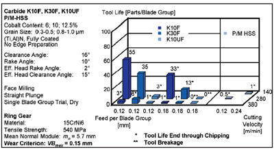
Figure 8—Tool life overview of the substrate variation.
The tools of the ultrafine grain carbide K10UF, however, obtained only inferior tool lives and chipped early even at relatively low cutting parameters (see Figs. 8 and 11). At high cutting speeds and/or feeds, tool breakage occurred during the first cuts. Through tool examination, contamination as well as grinding cracks could be excluded as potential reasons for tool failure. Obviously, the high sensitivity towards high dynamic load is characteristic for this tool material. The often mentioned twofold beneficial influence of the grain refinement for toughness and hardness might apply for the cutting edge stability at moderate dynamic or high static loads. High macroscopic loads on the tool body (not only the cutting edge area), however, can obviously lead to tool breakage earlier than they do for coarser grain grades. The key figure for toughness (tensile rupture strength) seems to show the opposite. The TRS value, however, is determined in a quasistatic bar-bending test and seems to have little significance for the material behavior at impact loads.
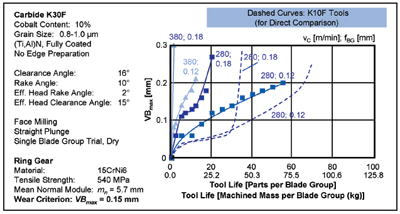
Figure 9—Wear charts for the K30F very fine grain carbide.
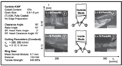
Figure 10—K30F tool wear mechanisms.
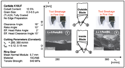
Figure 11—K10UF tool failure and wear.
In two trials, fully coated blades of a state-of-the-art P/M grade that is applied successfully in parallel axis gear hobbing, have also been applied for bevel gear cutting. The results are presented in Figure 8. At the same material removal rate as the lowest cutting parameter set of the carbide trials, these tools could not achieve acceptable tool lives. Even a change of the ratio of cutting speed and feed to a value which is more suitable for HSS (while keeping the material removal rate constant) did not bring about tool lives which are competitive with carbide. This is obviously due to the significantly lower red hardness of the P/M HSS or even due to an overcritical heat load on the tool, which is related to the chip length. For details about tooth cutting with P/M HSS tools, please see Reference 15. It can be assumed that P/M HSS blades can achieve better tool lives at lower cutting parameters. Their potential for high productivity automotive bevel gear cutting, however, appears to be not as high as the machining rate potential of cemented carbide.
Coating concept variation. In dry, high productivity tooth cutting of spiral bevel and hypoid gears with stick-type blades, there are two competing technologies in terms of tool reconditioning. After the first use, the blades either are reground and thus mechanically decoated only from the clearance sides or are reground from the clearance sides and the rake. In the first case, the tool can be used again with coated rake and uncoated clearance side. This brings about disadvantages with regard to tool substrate load, but supersedes a recoating process. In the latter case, the tool has to be recoated after every regrinding, since its rake would be uncoated during cutting otherwise. The technological advantages are, however, coupled with the need for coating deposition after each application.
In order to provide laboratory data for an economical assessment of the alternative concepts, a full factorial cutting speed and feed variation has been conducted with blades that have been mechanically decoated by grinding at the clearance sides. Their tool lives can be compared to the tool lives of fully coated blades with all other parameters kept equal.
Figure 12 shows the comparison of the tool lives. It is obvious that the tool lives of the fully coated blades are remarkably higher than the tool lives of the only-rake-coated blades. The difference with regard to tool wear behavior becomes apparent when comparing the wear charts of the blades (see Fig. 13). While the wear rate of fully coated blades decreases after the initiation wear, it remains at a constantly high value compared with blades that are uncoated on the clearance sides. Although, in this case, the performance of the two tool systems differs strikingly and by a large amount, it should be stated that it is possible that the difference might be less distinct with tools of different clearance angles or at lower cutting speeds.
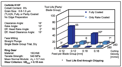
Figure 12—Tool life comparison between fully coated tools and only-rake-coated tools.
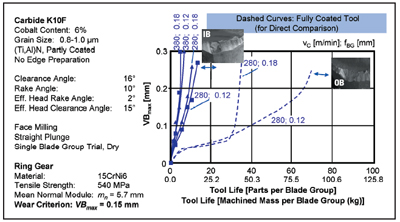
Figure 13—Wear charts of the only-rake-coated tools.
The cost effiency comparison of the tool systems is, naturally, highly influenced by the cost per coating deposition. The fact that coating prices differ significantly between the United States and Europe could be the main reason for the tendency that more fully coated tools are used in Europe than in the U.S.
Tool macrogeometry variation. Another important set of technological degrees of freedom besides substrate and coating specification and cutting parameters is the tool geometry.
In order to evaluate the influence of the blade macrogeometry on the wear behavior, tools with increased wedge angles (at tip and side) have been applied in a full-factorial variation of cutting speed and feed, and their tool wear progress has been compared to blades of standard geometry. The wedge angles have been increased by decreasing the clearance angle at the tool tip and side edges and by decreasing the side rake angle. On the one hand, the rake angle reduction results in a cutting force and power increase (Ref. 16). On the other hand, the shape stability and heat removal rate from the cutting edge are higher.
In Figure 14, the tool life comparison is presented. It is obvious that although the longest tool life was achieved with a conventional tool at the lowest machining rate, the average tool lives of the modified blades are notably higher than the average tool life of the conventional blades in this full-factorial trial.
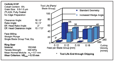
Figure 14—Comparison, standard geometry vs. increased wedge angle.
Moreover, the sensitivity of the modified blades towards changes of applied cutting parameters and loads is clearly lower than the sensitivity of the standard-geometry blades. While the standard blades show a tool life drop at increased machining rates, the tools with higher shape stability reach a similar tool life, no matter which cutting parameter set in the wide trial range has been applied.
This difference between standard tools and modified blades can also be seen in the wear progress curves in Figure 15. While the wear curves of the standard geometry tools vary considerably, depending on which cutting parameters have been applied, the modified tools showed similar wear progress at all used cutting parameter settings.
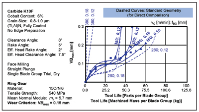
Figure 15—Wear charts of the geometry variation.
Concept of a New Blade System
While small changes of technological parameters, such as rake and clearance angles, chip thickness or carbide cobalt content are intended to bring about steplike improvements, the choice of changing more basic settings provides the chance to establish a technological leap. Therefore, a tool concept, which has a fundamentally different cut segmentation than the state-of-the-art systems, is presented below. The statements below apply on the actual tool tip and are considered regardless of the tool shaft, since the idea is theoretically applicable to round, square, rectangular or pentagonal blade blanks or even cutting inserts which are mounted to a rigid cutter head body.
In Figure 16, three state-of-the-art blade systems for spiral bevel and hypoid gear manufacturing and the WZL tool concept are presented.
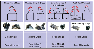
Figure 16—Cut segmentation of different tool concepts.
The fundamental advantage of the three-flank blade (left) is the fact that only one blade (per group) is required to cut the teeth. Therefore, it can theoretically achieve high material removal rates at a given chip thickness value. However, the number of degrees of freedom in terms of tool design is low since the side rake angle must be set to zero on both sides in order to avoid a negative rake angle on one side. Consequently, the tip tool cutting inclination ?s is set to zero, too. This results in higher specific cutting forces (higher cutting edge load) and more agitated cutting. Additionally, the V-shaped chip cross-section (a three-flank chip) leads to a critical chip rolling behavior since the chip shape hardly allows for decent coiling of the chip.
For kinematic reasons, the three-flank blade can only be applied for face milling operations (Ref. 17).
The system of outside and inside blades avoids the disadvantages of V-shaped chips by separating the theoretical three-flank chips into two two-flank chips. Two-flank chips require less room for coiling up, but they have also turned out to tend to chip drag or buckle and to tear and collide with the opposite tooth flank. Due to the cut segmentation, a minimum number of two blades per blade group is required. The blades can, however, be manufactured with positive side rake angles and thus also with a low tip tool cutting inclination ?s. Both can lower the cutting force and the impact load on the tool. The system of inside and outside blades can be used for face milling and face hobbing operations.
The third system, which consists of inside, outside and bottom blades can also be applied for face milling and face hobbing and has the highest number of degrees of design freedom. Through a consequent cut segmentation into mere one-flank chips, an advantageous chip collective is generated, and chip drag and buckling are avoided. Positive side rake angles can be established, as well as any tool cutting inclinations at the cutting edges. However, the extended chip segmentation into three chips requires a minimum of three blades per blade group. This main disadvantage has led to the fact that this tool concept is barely applied in high volume production nowadays.
The WZL tool concept combines the advantages of cutting only one-flank chips with a tool system that only requires two blades per group. The tip blade can be understood as a modified three-flank blade which is retracted at the side edges. The side blade can be seen as a modified three-flank blade which is retracted at the tip. Since no chip drag or buckling is expected, these tools are likely to achieve longer tool lives. The avoidance of multiflank chips, however, is not the only theoretical advantage of the new tool concept (see Fig 17).
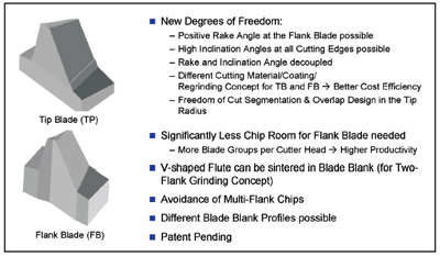
Figure 17—A possible design of the WZL tool concept and gained degrees of freedom.
Since the side cutting edges of the side blade do not touch each other, the rake can be featured with a groove that establishes a positive rake angle on the side edges, although the side blade cuts on both opposite sides. The different chip segmentation hence brings about some theoretical advantages of this tool system towards the system of outside and inside blades in face milling. Since the thicknesses of tip and side chips are very dissimilar, the design of outside, inside or even three-flank blades is always complicated by the fact that a trade-off between the different requirements has to be met. The new tool system, however, allows for adapting the side blade to the specific needs of this part of the tool and for adapting the tip blade accordingly. It could, for example, turn out to be the most cost efficient way to cut teeth with different cutting materials, coatings or coating concepts (full/rake only) on side and tip blades.
For these reasons, it seems promising to perform further research and development in order to make a fact-based assessment of the tool performance. To reduce the number of required machining trials, thorough design of experiments and a closed-loop tool development, as suggested in Reference 18, seems appropriate. In the near future, the influence of the tool shape and the cutting parameters on both the cutting forces and the chip coiling and flow behavior will be studied with high-speed photography and force measuring in a new test rig at WZL.
The presented basic concept as well as the subsidiary ideas have been documented in a patent application and are protected as main and subsidiary claims (Ref. 19).
Summary and Outlook
In a thorough cutting parameter variation, the effects of cutting speed and feed on the tool life of bevel gear cutting blades with conventional design were determined. While the cutting speed shows a negative effect on the tool life in the whole considered range, there appears to be an optimum feed for tool life around fBG = 0.15 mm per blade group. Above and below this feed, the tool lives are significantly lower. Particularly for the very low feed of fBG = 0.03 mm, which is characteristic for finishing operations (or the finishing part of a completing operation), the tool life drops considerably. These findings cannot be transferred ideally into industrial production since dynamic machine stiffness and chip room constraints can cause problems that lower or destroy process robustness. The studies, however, show the potential of present-day tools that has to be exploited for future enhancements of tooth cutting.
The negative effect of the cutting velocity in the range vc = 280–380 m/min was observed on tools with conventional geometry design for each tested coating, each cutting material and on tools with a cutting edge preparation as well as on very sharp tools which were not rounded.
The very fine grain carbide grades K10F and K30F showed the best performance. In contrast to that, unacceptable tool lives were obtained with the ultrafine grain carbide K10UF and P/M-HSS blades.
The comparison of the wear behavior of fully coated tools versus only-rake-coated tools showed a distinct predominance of fully coated tools. The tool lives of the tools with uncoated clearance faces were lower by a very large amount.
One approach to improve the tool shape stability is through an increase of the wedge angle at the tip and/or flank edge. The modified tools were much less sensitive towards a high advancement of the cutting speed and/or feed. Since the trials showed a high potential for tool improvement but did not allow an assessment of the influence of the particular technological angles, further investigation appears to be promising.
Finally, a new face milling cutting tool concept which was developed at WZL has been presented. The concept tool has a number of theoretical advantages in relation to currently available tools. The consequent exploitation of these potentials might lead to a notable improvement of chip flow and tool life. A prerequisite for a successful implementation is, however, diligent development, followed by blade prototyping and testing in machining trials.
Acknowledgment
The studies which are described in this article were funded by the Research Association for Machine Tools and Manufacturing Technology (Forschungsvereinigung Werkzeugmaschinen und Fertigungstechnik (FWF)) and the German Federation of Industrial Cooperative Research Associations (Arbeitsgemeinschaft industrieller
Forschungsvereinigungen e.V. AiF) (Project # AiF-Nr. 13713 N/1)
Republished with the friendly permission of VDI from: VDI Gesellschaft Entwicklung, Konstruktion, Vertrieb (Editor), International Conference on Gears, Vol. 2, VDI Report 1904, VDI-Verlag, Düsseldorf, Germany, 2006, pp. 843-863 (first publication). In the VDI report, the article was titled “Approaches for Manufacturing Efficiency Enhancement and Tool Optimisation in Dry High Speed Bevel Gear Manufacturing.”
References
1. Stadtfeld, H.J. “Dry Cutting of Bevel and Hypoid Gears,” Gear Technology, Vol. 15, No. 3, 1998, pp. 39–43.
2. Engemann, K.H. “Herstellungs- verfahren für bogenverzahnte Kegelräder – Neue Maschinen zur High Speed Cutting - Trockenbearbeitung,” Paper from the seminar Die wirtschaftliche Herstellung von Stirn- und Kegelrädern, Technische Akademie, Esslingen, Dresden-Langebrück, Germany, 2000.
3. Schott, E., M. Rich, S. Keisers and S. Hinderer. “Trockenfräsen und Schleifen von bogenverzahnten Kegelrädern - die ideale Kombination für die Zukunft?,” Paper from the seminar Innovationen rund ums Kegelrad, WZL, RWTH Aachen, Germany, 2001.
4. Stadtfeld, H.J. “Zukunftsweisende Kegelrad-Verzahntechnik – Herstellung, Messung und Optimierung,” Corporate Publication, The Gleason Works, Rochester, NY, 2001.
5. Stadtfeld, H.J. “Phönix II - Die Säule der zukünftigen Kegelradherstellung,” Corporate Publication, The Gleason Works, Rochester, NY, 2001.
6. Bouzakis, K.D., N. Michailidis, J. Anastopoulos, S. Kompogiannis, G. Erkens and P. Roudnik. “Geometry and Coating Parameters Effect on Cemented Carbide Sticks Cutting Performance Used in Bevel Gear Manufacturing,” Surface and Coatings Technology, Vol. 153, April 15, 2002, pp. 148–154.
7. Landvogt, A. “Qualitätsregelkreise in Fertigung und Montage,” Paper from the seminar Innovationen rund ums Kegelrad, WZL, RWTH Aachen, Germany, 2004.
8. Mikoleizig, G. “Neue Wege in der Kegelradmesstechnik – hohe Informationsdichte, dynamisch und genau,” Paper from the seminar Innovationen rund ums Kegelrad, WZL, RWTH Aachen, Germany, 2004.
9. Müller, H. “Neue Wege in der Prozesstechnik,” Paper from the seminar Innovationen rund ums Kegelrad, WZL, RWTH Aachen, Germany, 2004.
10. “Knochentrocken - Neues Maschinen- konzept ermöglicht Wälzfräsen ohne Öl,” Maschine und Werkzeug, Vol. 99, No. 6, 1998, pp. 48–50.
11. Wiener, D. “Entwicklungsstand bei der Fertigung von Kegelrädern,” Paper from the seminar Innovationen rund ums Kegelrad, WZL, RWTH Aachen, Germany, 1999.
12. Stadtfeld, H.J. “1 Phoenix ersetzt 3 bis 6 CNC,” Produktion, Issue 13, 2003, Landsberg/Lech, Germany.
13. Sattelberger, K., and G. Fittigauer. “Kegeltriebtechnologie im Wandel – Produktion heute und morgen,” Paper from the seminar Innovationen rund ums Kegelrad, WZL, RWTH Aachen, Germany, 2004.
14. Wöhe, G. Einführung in die allgemeine Betriebwirtschaftslehre, Verlag Franz Wahlen, München, Germany, 1986.
15. Klocke, F., M. Kleinjans and A. Klein. “Mikrometer für Millisekunden – Hartstoffschichten zur Leistungssteigerung beim Wälzfräsen,” VDI-Z Integrierte Produktion, November/December 2004, p. 67ff.
16. König, W., and F. Klocke. Fertigungsverfahren Drehen, Fräsen, Bohren, 5th Auflage, Springer Verlag, Germany, 1997, p. 73ff.
17. Grundlagen der Kegelradverzahnung Course “T1,” Klingelnberg AG Gear School, 2004.
18. Kammermeier, D. “Optimierung eines HPC-Fräswerkzeugs mit Closed Loop Development,” Paper from the 4th Chemnitzer Produktionstechnischen Kolloqium, Verlag Wissenschaftliche Skripten, Chemnitz, Germany, 2004, p. 640.
19. Klocke, F., and A. Klein. “Schneidwerkzeug mit vorteilhafter Schnittaufteilung zum Verzahnen von Werkstücken mit einem Stirnmesserkopf,” Patent Application, Germany, December 2005.
Prof. Dr.-Ing. Fritz Klocke is head of the Chair of Manufacturing Technology at the Laboratory for Machine Tools and Production Engineering (WZL), a part of Aachen University of Technology in Germany. Also, he is director of the Fraunhofer Institute for Production Technology in Aachen, Germany.
Dipl.-Ing. Alexander Klein is team leader of the WZL research department Gear Manufacturing Technology. Also, Klein performs research in bevel gear manufacturing.
Comment on this article by sending e-mail to publisher@geartechnology.com
