Manufacturing Net-Shaped, Cold-Formed Gears
Dr. Dennis M. Engelmann
Management Summary
A net-shaped metal forming process has been developed for manufacturing quality, durable, high-yield and cost-efficient gears for high-volume production. In this article, the development of net-shaped cold-formed gears (CFG) by using the divided flow method will be presented, along with their suitable applications. The manufacturing technique and equipment will be introduced, as well as the advantages and limitations. Applicable materials and heat treatment practices will also be discussed. Gear tooth inspection charts will be presented and compared to conventional manufacturing methodologies.
(Printed with permission of the copyright holder, the American Gear Manufacturers Association, 500 Montgomery Street, Suite 350, Alexandria, Virginia 22314-1560. Statements presented in this paper are those of the authors and may not represent the position or opinion of the American Gear Manufacturers Association.)
Introduction
Cold forming/cold forging is a bulk metal forming process where a metallic workpiece is plastically deformed into a tool by a press. The workpiece and tooling are at room temperature—i.e., they are not pre-heated, as in the case of hot forging.
The advantages of using a cold forming process to manufacture parts are: 1) there is less material waste since material is being displaced and not removed; 2) the parts can be made at very high production rates; 3) the parts are strong due to the work hardening of the material; 4) the parts have tight tolerances; and 5) the parts have excellent surface quality.
Cold forming by the divided flow method is a process where a workpiece is simultaneously pressed from an upper punch and a lower punch, allowing the material to flow radially outward into the die cavity (Fig. 1). This process is typically used for forming rotational symmetric components.
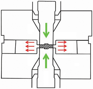
Figure 1—Cold forming by the divided flow method.
A net-shaped or near-net-shaped forming process is one where no or minimal secondary and/or finishing operations are necessary. A net-shaped gear is a gear where the teeth do not need to be machined or finished.
Development
To begin development of cold forming gears, finite element analysis (FEA) was used to determine how much forming load is required, how the material will flow, and how much the tools will deflect (Fig. 2).
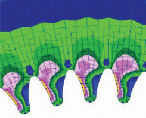
Figure 2—Gear die stress distribution.
Since metal forming involves movement of large amounts of material, a plastic deformation (non-linear) finite element software program is required. Today there are over a dozen commercially available FEA software packages capable of simulating metal forming processes, cold or hot.
An advantage of using FEA simulation during the development phase is to be able to determine the overall effects of parameters on the results; e.g., the effects of the punch geometry on the material flow, the effects of the material alloying and processing on the forming load, etc. (Fig. 3). As a developmental tool, FEA simulation allows the user to test several “what if” scenarios without having to manufacture expensive “hard” tools. FEA simulation can also be used to help determine what type and size of manufacturing equipment is required to cold form a family of gears.
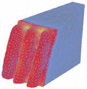
Figure 3—CFG strain distribution.
The FEA simulation results were used to conduct an initial feasibility analysis to determine the process limitations and manufacturing equipment requirements, and to estimate if the process yields a competitive product.
Processes and Equipment
Net-shaped cold forming of gears does not require any additional manufacturing processes over the traditional gear manufacturing process. Simply put, the gear cutting process is replaced by a metal forming process. Furthermore, conventional pre-and postprocessing operations are applicable. Figure 4 illustrates a typical cold-formed gear process flow.
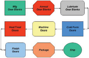
Figure 4—CFG process flow chart.
Gear materials. The cold formability of steel is dependent primarily on the amount of carbon in the steel. The lower the amount of carbon content— e.g., 8620 vs. 8640—the smaller the forming load and the less the tools will be stressed. The alloy content and the raw material processing also play a role in how the material will flow—e.g., 1040 vs. 4140. For most gear configurations, the common gear materials ranging from low carbon steels (1020) to medium carbon-alloyed steels (4340) can be formed. If the carbon content is above 40 points, it is better to consider hot forging, which will improve the metal flow and reduce the forming loads.
Gear blank manufacturing. As with many manufacturing processes, it is important to start with an inexpensive blank, whether it is a blank turned from bar stock or a blank cold-formed from coiled wire. The optimal blank manufacturing process depends on the size and shape of the blank required.
If a gear blank is under 50 mm, then the blanks could be cold-formed using coiled wire on a cold header at speeds ranging from 60 to 180 parts-per-minute. If a gear blank is larger than 50 mm, then it could be turned from bar stock or in some cases hot-formed.
In order to cold-form gears, it is generally better to anneal the gear blanks to remove the residual stresses and any “work hardening” effects from prior processing of the material. Annealing softens the gear blanks and makes them more formable, which reduces the forming load required to deform the material.
Since the gear blanks will be cold-formed in a tool cavity, lubricants and coatings must be used in or der to avoid galling. Forming oils and/or zinc phosphate coatings are typically used to coat the blanks. PVD (physical vapor deposition) coatings such as TiCN (titanium carbo-nitride) are used to coat the tools.
Forming press. In order to plastically deform the workpiece into the die cavity, a forming press is required. For the divided flow method, the press can be either a mechanical or hydraulic forming press, depending on the complexity of the part and accuracy required. The main advantage of a single-action mechanical press is the high productivity rates. However, a hydraulic press can have more than one action and deliver desired forming loads and speeds at specific points throughout the stroke of each action with precision.
For the development and production of cold-formed gears, a 1,200 ton, triple-action CNC hydraulic press is used (Fig. 5).
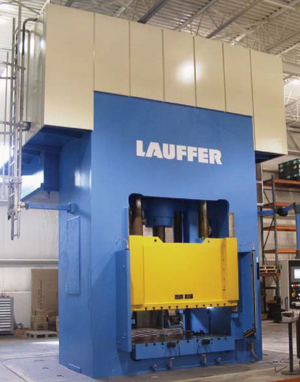
Figure 5—Triple-action hydraulic press.
Gear Tooling
Since cold forming processes occur at room tem perature, the forming loads required to plastically deform steels are very high. Hence, the stresses in the tooling are also very high, which can lead to pre mature tool failure. Advancements in tool steels and the development of more formable steels has enabled cold forming processes to be applied to more complex, precise components that were not possible earlier.
Cold form gear tooling consists of a die set, gear die, punches and die clamping rings (Fig. 6). Since these tools touch the workpiece, they are unique for each gear. These tools have a limited tool life due to the high stresses (fatigue) and frictional contact (wear), and as such are considered to be “perishable” tooling.
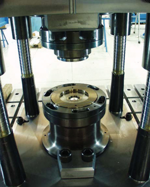
Figure 6—Gear-forming tools.
The die set that holds the perishable tools is considered to be durable tooling. The durable tools are not unique for each gear and have a much longer tool life because they typically are not as highly stressed and do not experience as much wear.
Standard tool steels such as shock-resistant (S); molybdenum (M) and tungsten (T) high-speed; water (W), oil (O) and air (A) hardening; and high-carbon/high-chromium (D) tool steels can be used for cold forming gears.
Due to the high forming loads during cold forming, the gear tooling elastically deflects. When the tool deflection is consistent from part to part, it is possible to compensate for the elastic deflection during the manufacturing of the perishable tools. Generally, a gear die should be manufactured a few quality levels better than the final product.
Machining operations. After the gear teeth are cold-formed, the gears are said to be in the “green” state because they have not yet been hardened. In this state, features on the gear that could not be cold-formed--such as chamfers, grooves, clutch face features, etc.--can be machined using standard CNC equipment.
Heat Treatment. The heat treatment of cold-formed gears, as with conventional gear manufacturing processes, depends on the base material. Cold-formed gears of lower carbon content can be case hardened, while medium carbon content gears can be through hardened. The use of heat treat baskets aids in the handling of the gears and the uniformity of the hardening results (Fig. 7). Cold-formed gears can also be induction hardened inline.
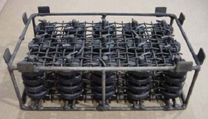
Figure 7—Gear heat treat baskets.
Finishing operations. After hardening of the gears, the center hole can be honed, the faces or any bearing surfaces can be ground and, for high quality gears, the gear teeth can be ground, all using standard production equipment.
Gear Quality
The gear quality, like in all conventional gear manufacturing methods, is dependent on the manufacturing process tolerances and consistencies. Since a gear blank is formed in a closed die, the volume (weight) of the gear blank is important. If there is not enough material, there will be un derfill in areas of the gear. If there is too much material, the die cavity will be overfilled, causing excessive tool stresses and eventually breaking the die.
The forming press is more than just a big hammer to smash the gear blank. In fact, the more accurately the press can be controlled, the more accurate the gears will be. The more consistently the press can apply the forming load, the more consistent the gears will be from part to part.
The gear die has the largest influence on the gear quality. As stated earlier, the gear die tooling will be made a few quality classes better than the desired gear quality. In addition, the elastic deformation of the tooling must be compensated for and incorporated into the tool design. The selection of tool materials, coatings and manufacturing methodologies is very important in making a high-quality gear die.
Machining, finishing and heat treatment affect a cold-formed gear’s quality as much as and in the same ways as they do for a cut gear.
Depending on the gear configuration, a net-shaped, cold-formed gear will typically yield an AGMA Q8–Q9 finished quality gear.
Advantages of Cold-Formed Gears
The advantages of manufacturing gears by cold forming are: 1) high production rates; 2) effective material usage; 3) small tooth-to-tooth variation; and 4) high strength and high durability.
High production rate. Since all of the teeth are formed simultaneously, the time it takes to fill the die cavity is only a few seconds. Cycle time varies based on the size and configuration of the gear, but most gears can be cold formed at rates of 2–10 parts per minute.
Effective material usage. An advantage to the closed die forging process is that material is not being removed, but displaced. This typically results in a 5–10% material savings just from forming the gear teeth as opposed to cutting them.
An additional material savings of 10–30% is possible by designing a thinner web (Fig. 8). The forming punches can be designed so that a thinner symmetrical web can be formed without “putting chips on the ground.” Hence, a lighter blank can be used with shaped forming punches.
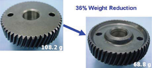
Figure 8—Material savings.
Small tooth-to-tooth variation. As can be seen in Figure 9, a cold-formed gear has less tooth-to-tooth variation than hobbing, since all of the gear teeth are formed simultaneously in a precise gear die. This could result in a smoother, quieter and longer-running gear.
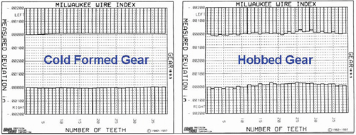
Figure 9—Comparison of tooth-to-tooth variation for a cold-formed gear and a hobbed gear.
High strength and high durability. Cold forming steel induces local work hardening into the material which will yield a stronger product. As can be seen in Figure 10, most of the work hardening occurs in the root. Durability tests have shown that cold-formed gears can also withstand higher impact loads than powder metal gears.
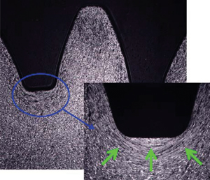
Figure 10—Strain hardening.
Applications and Limitations
To be competitive with conventional gear manufacturing processes, a cold-formed gear must be manufactured so that it can economically replace an existing gear. Some potential applications of cold-formed gears are in the automotive, recreational vehicle, power hand tool, lawn & garden, appliance, and gear motor industries.
As with any process or product, there are physical and economical limitations to its applications. Loose, flat spur and helical gears are good candidates for net-shaped cold-forming by the divided flow method (Fig. 11). Some gears with hubs or webs can be designed for cold forming. Gears with large, asymmetrical protrusions or pockets cannot be net-shape cold formed. These types of features are best done by machining.
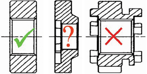
Figure 11—Gear configurations.
The size limitation of cold-formed gears is dependent primarily on the manufacturing equipment. The larger the gear and the less the material is formable, the larger the forming press required. The smaller the gear, the higher the tool stresses.
Medium- to fine-pitch gears are good candidates for cold forming, but large-pitch gears should not be excluded, depending on the configuration. The larger the pitch diameter to face width ratio (PD:FW), the easier it is to form the gear. The closer the PD:FW ratio is to one, the more difficult it is to form the gear teeth uniformly. The higher the helix angle, the more the tooling will be stressed and deflect. The higher the gear tolerances, the lower the tool life.
Even after compensating for the elastic tool deflection, it is not possible to consistently cold form gears above AGMA Q9 class. It is, however, possible to grind a cold formed gear to improve its quality class while capturing the other advantages of a cold-formed gear stated in the previous section. In other words, a near-net-shaped, cold-formed gear could be ground to yield an AGMA Q10 or higher quality gear.
Lastly, due to the large capital investment for the forming press and the high-quality gear die required, it is normally not economical to cold form gears for low annual volume productions. In addition, since the gear die cannot be easily modified, the process is best for long-term programs where the gear tooth geometry does not change often.
Closing Remarks
The process of net-shaped cold-forming gears by the divided flow method was introduced. The manufacturing processes and equipment, the advantages and limitations, were discussed.
High-volume, loose, flat spur and helical gears with large pitch-diameter-to-face-width ratio in the AGMA Q8 to Q9 quality classes are good candidates for this technology.
References
1. Lange, K. Handbook of Metal Forming, McGraw-Hill Book Company, 1985.
2. Ewert, R. Gears and Gear Manufacture–The Fundamentals, Chapman & Hall, 1997.
3. Harada, K. and H. Kanamaru. “Gear Forming Method,” United States Patent No. 5746085, 1998.
4. Ishikawa, H., S. Ishihara and T. Arima. “Helical Gear Production Method and Producing Device There fore,” Japanese Patent No. 11010274, 1999.
5. Keppler-Ott, T. “Optimization of Lateral Extrusion of Helical Gears,” Doctoral Dissertation from the Institut für Umformtechnik, Universität Stuttgart, Germany, DGM Verlag, 2002.
6. Sweeney, K. “Cold Forming of Helical Gears,” Doctoral Dissertation from RWTH Aachen, Germany, Shaker Verlag, 2000.
7. Tekkaya, A.E. “Report—Subgroup Process Simu lation International Cold Forging Group,” ICFG Doc ument No. 15/02, 2001 Workshop in Ankara, Turkey.
8. Meidert, M. and M. Hänsel. “Net shape cold forging to close tolerances under QS 9000 aspects,” Journal of Materials Processing Technology, Volume 98, Is sue 2, 29 January 2000, Pages 150–154.
9. Kondo, K. “Profitable Net Shape Forging of Auto motive Components” (in German), International Conference on New Developments in Forging Technology, Fellbach, Germany, 2005.
Dr. Dennis M. Engelmann received his bachelor of mechanical engineering degree from Fenn college of engineering in 1988, his Master of Science in mechanical engineering from Ohio State University in 1990, and his Ph.D. in metal forming from the Technical University of Budapest in 2001. He is currently the technical manager of new process and product development at Milwaukee Wire Products, where he has worked since 1988. Dr. Engelmann spent nine years in Germany working with European automotive OEMs, tool suppliers, press manufacturers and material suppliers in the areas of deep drawing and cold forming. He began work in 1998 on the development of cold-formed gears in Germany and Japan, and in 2003 began production for Milwaukee Wire of a cold-formed gear for a hand power tool manufacturer. Dr. Engelmann has authored and co-authored international publications on metal forming and has given technical presentations in both German and English.
