Investigation of the Manufacturability of Topological Modifications Using Adapted Kinematics for Gear Skiving
Nomenclature a axial distance b2 gear width c𝛽 crowning da0 tool tip diameter da2 gear tip diameter fa axial feed rate mi polynomial coefficient mn0 tool module mn2 gear module NC Numerical Control z0 number of teeth of the tool z2 number of teeth of the gear 𝛼n0 tool profile angle 𝛼n2 gear profile angle 𝛽0 tool helix angle 𝛽2 gear helix angle 𝛥 difference between modifications 𝛴 axis crossing angle 𝜑 twist angle |
Introduction
Gears that are provided with tooth flank modifications have advantages over unmodified variants (Ref. 1). These advantages include improved acoustic excitation behavior, improved load-carrying capacity, or an increase in efficiency (Refs. 2, 3). The degree of optimization can be increased by using topological modifications, compared to the standard modifications known by the standard (Refs. 2, 3, 4, 5).
The increasing industrial relevance of tooth flank modifications can be traced back to a radical change in the automotive industry. Increasing environmental awareness is presenting car manufacturers with new challenges. One of these challenges is to make automobiles more efficient and thus more resource-efficient in their consumption. The transmission is one component that can be optimized in terms of weight and noise emissions (Ref. 6). Tooth flank modifications are usually applied to the gears in the last step of the gear manufacturing process chain, hard finishing (Ref. 7). For the manufacturing of this modification, established manufacturing processes such as profile or generating grinding are generally used (Ref. 7).
A manufacturing process that has received little attention in this respect is gear skiving. It is only recently that gear skiving has become a focus of gear manufacturing (Refs. 8, 9). With gear skiving, a process is available that is suitable for the machining of gears in soft and hard conditions (Ref. 10). Gear skiving can be combined with the production of tooth flank modifications. However, the application possibilities and limits have hardly been investigated so far.
State of the Art
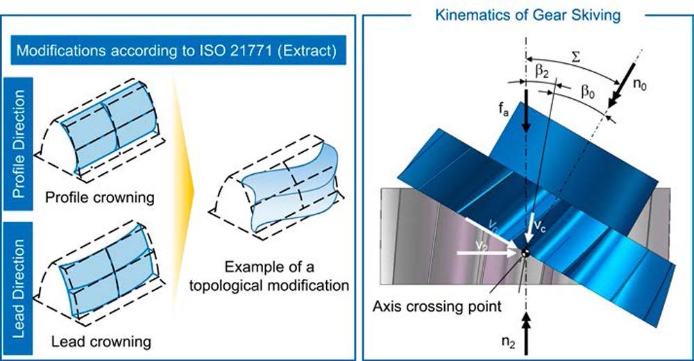
According to ISO 21771, topological modifications are described as a freely definable modification amount on the grid of a tooth flank (Ref. 11). In contrast to standard modifications, which require at most two defining parameters, a definition with three parameters is necessary (Refs. 4, 11). Two of the parameters describe the location on the grid using coordinates in lead and profile direction. The third parameter represents the amount of modification at the previously defined location. Topological modifications can thus have gradients that go beyond the linear and quadratic gradients of standard modifications (Ref. 4). A description of the courses by a polynomial of higher order (with a degree greater than two) is possible, as well as a periodic modification in the form of a wave (Ref. 2), see left side of Fig. 1. For the manufacturing of topological modifications, generating grinding or profile grinding was mainly used (Refs. 12, 13). The manufacturing of topological modifications by gear skiving has not been investigated so far.
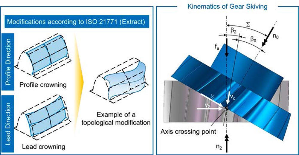
Figure 1—Flank modifications and gear skiving kinematics (Refs. 14, 11).
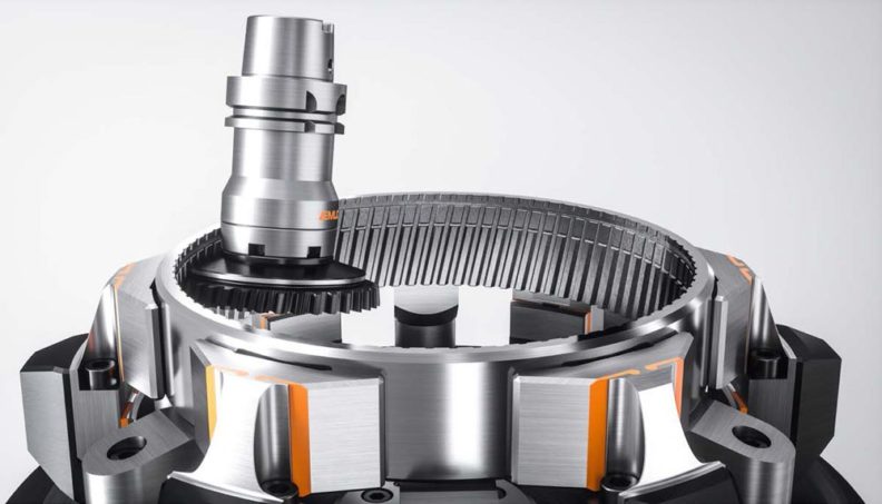
Gear skiving is a manufacturing process with a defined cutting edge for machining periodic profiles (Ref. 14). It is suitable to produce both internal and external gears as well as worm gears (Ref. 15). The process is mainly used when gear hobbing is not possible (Ref. 10). This is especially the case for producing internal gears and gear shafts with interfering contours (Ref. 8). Due to progressive developments in the field of CNC control of machine tools, series production with gear skiving is possible (Ref. 8). Hard skiving is an additional process variant that allows hard fine machining of the tooth flanks (Ref. 16).
The kinematics of gear skiving are shown graphically on the right side of Figure 1. The rotational axes of the workpiece and the tool are inclined to each other by the axis crossing angle 𝛴. The axis crossing angle results from the sum of the helix angles of the tool 𝛽0 and the workpiece 𝛽2, cf. Fig. 1 (Ref. 14). If the axis cross angle 𝛴 is increased starting from 0 degrees, the rolling motion becomes a screw rolling motion (Ref. 15). The screwing motion results in a cutting speed vc, which leads to chip removal if the axis crossing angle 𝛴 is sufficiently large.
Objective and Approach
By applying topological modifications, a gear can be improved in terms of acoustic excitation behavior, efficiency or load-carrying capacity compared to standard modifications. The manufacturing of such modifications has been researched for established manufacturing processes such as generating or profile grinding. These processes are however not suitable for internal gears, whereas the gear skiving process is suitable for internal and external gears. Investigations into the manufacturability of topological modifications utilizing gear skiving are not available.
In the first step of this research, the kinematics of the tool and the workpiece required for producing the modifications are derived. The modifications are varied for the flank lines starting from a linear and a quadratic deviation up to a polynomial deviation of a higher degree. Based on these kinematics, an NC code is created for the machine control. For the derivation of the necessary kinematics, the knowledge about the positioning of the axes in the machine coordinate system is relevant. In the next step, external gears are manufactured using the previously defined kinematics in a gear skiving process. Finally, the lead deviations and the topography are measured. Based on the available results, it can be evaluated to what extent topological modifications can be applied by gear skiving.
Design of Experiments and Test Setup
Trials to investigate the manufacturability of topological modifications were carried out on a Gleason Pfauter 300 PS gear-skiving machine. A two-flank machining strategy in the soft state was selected for the application of the lead modifications. The material used was a 20 MnCr5 steel commonly used for gears. A gear skiving process with 25 cuts was designed for cutting the gears. The infeed over all cuts was defined with a degressive strategy based on a maximum chip thickness of hcu,max = 0.15 mm. The modified kinematics were applied exclusively in the last quality-critical cut. A cutting speed of vc = 60 m/s was kept constant for all cuts. An axial feed rate of fa = 0.05 mm was selected for the final shape-forming cut. A low feed rate of this magnitude results in minimal process-related flank deviations, such as feed marks.
At an increased feed rate fa, there is a possibility that process-related deviations will override the modifications applied by the adapted kinematics. Based on the tool and workpiece data, an axis crossing angle of 𝛴 = -20 degrees was specified. For the investigations, a right-handed tool with an outer diameter of da0 = 160 mm and a number of teeth of z0 = 29 was used. Both the pressure angle an0 and the helix angle 𝛽0 were 20 degrees. The cutting material used was PM high-speed steel coated with AlCrN. Table 1 shows the most important gear and tool data.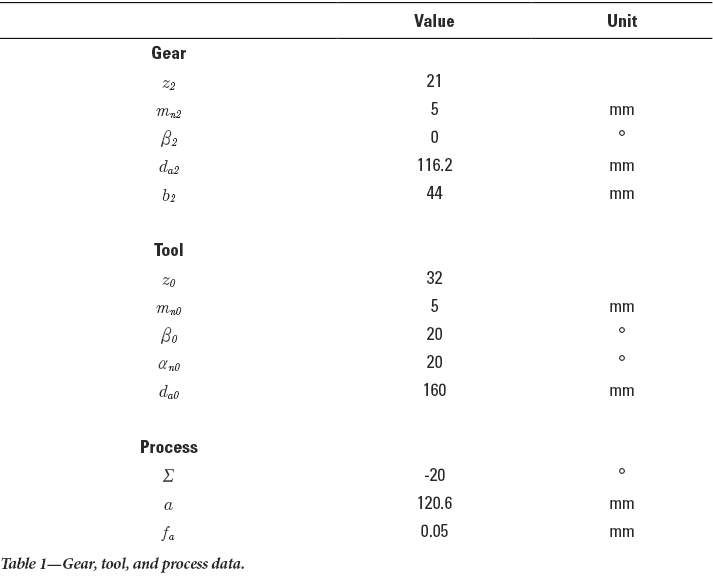
The general procedure for varying the kinematics is shown in Figure 2. When varying the center distance along the tooth width b2, the kinematic parameters axis crossing angle 𝛴 and twist angle 𝜑 remain constant. In addition to the center distance variations, which can be described by a polynomial of any degree, a gear with an end relief was manufactured. To produce an end relief, the specification of a discontinuous differentiable axis motion is mandatory. A possible discontinuous axis motion is shown in purple Figure 2 on the left. In addition to the center distance, the axis crossing angle 𝛴 and the twist angle 𝜑 can also be varied, see Figure 2 center and right. Varying the twist angle 𝜑 causes a shift of the cut from one flank side to the opposite flank side. The change in position of the workpiece relative to the tool due to a twist angle variation is shown as an example in Figure 2. A variation of the axis crossing angle 𝛴 leads to a change of the tool profile projected into the tooth gap. An example illustration of the variation is shown in the center of Figure 2. Depending on the selected axis crossing angle 𝛴, the additional tilting around the y-axis results in an increase or decrease of the tool profile projected into the cutting plane of the tooth gap. Due to the tilting of the tool profile, uneven material removal in profile and flank direction is to be expected during manufacturing.
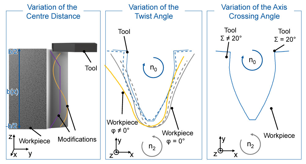
Figure 2—Overview of kinematic adjustments.
Transfer of the Kinematics into the Machine Control
The use of simulations enables the optimization and testing of processes in advance of their execution in the manufacturing environment. The translation of the simulated motions into a machine-readable language, such as NC code, is necessary to take advantage of the simulations in practice. This chapter describes the development of a converter capable of translating discrete-time kinematics from a simulation into NC code for a machine control system.
Development of an NC Converter
To transfer the kinematics, a converter was developed that can translate discretized time kinematics from a simulation into NC code for machine control. The kinematics derived in a .MPF file were read in and processed by the Sinumerik 840D SL machine control from Siemens. Discretized time kinematics refers to the movements of a system that calculates the axis movements of the tool and workpiece in time steps. For the development of an NC converter, the understanding of the working area and the axis positioning was of fundamental importance. The required axis positions in the machine coordinate system were derived from existing data and taken into account.
The simulation used to generate the kinematics had a different origin in the coordinate system to the machine coordinate system itself. Therefore, the axes for the machine control had to be shifted to generate accurate kinematics. The machine coordinate system refers to the area in which the machine actually operates, while the simulation coordinate system represents a virtual area in which the kinematics are generated. The differences between the two systems could induce faulty machine control if the axis positions were not correctly considered. An example of the procedure for transferring the kinematics to the machine control system is shown in Figure 3. Starting from a manufacturing simulation, kinematics was defined which describes a variation of the center distance a along the gear width b2. In addition to the center distance variation, the traverse path in the z-direction is also displayed. The kinematics are described discretely in time in a period from t = 1 to t = 3. Due to a shift in the coordinate system in the working area, it is necessary to perform a zero-point shift. In this example, the shift of the z axis is necessary. In addition, the run-in and run-out defined by the machine are taken into account and coupled with the previously derived kinematics. This is illustrated by an extension of the machining period, cf. Figure 3.
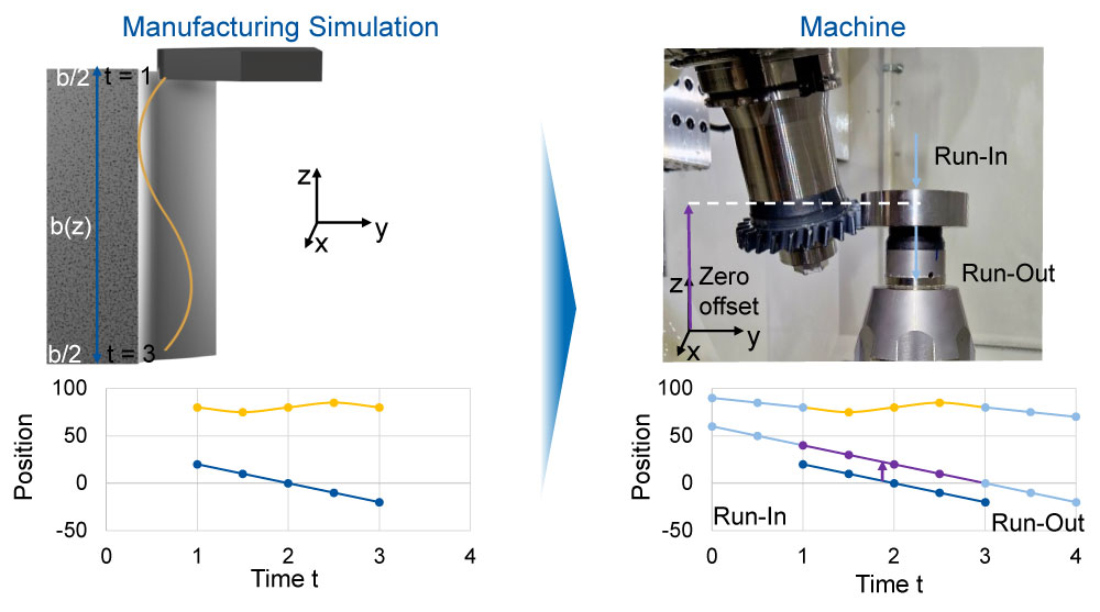
Figure 3—Method for converting kinematic data.
Knowledge of the working area and axis positioning enabled the NC converter to generate accurate and effective kinematics. By using the correct axis positioning in the machine coordinate system, the accuracy of the conversion was maximized. Then, the path curve was discretized. Here, the time-location information was divided into discrete steps to ensure a smooth transfer of the motions to the NC code. The velocity was kept constant by explicitly specifying the feed rate. A special feature of the converter is that it recognizes which axis has been modified and adjusts the path curve for the corresponding NC code. This meant that the simulated movements could also be accurately implemented using the machine control. Absolute specifications were used for changing the axis distance parameter as well as for varying the twist angle. For a variation of the twist angle, the converter enabled the generation of an NC code with relative position specification to execute the movements of the machine correctly even with changes in the twist angle 𝜑. To transfer the kinematics, a converter was developed that can translate discretized time kinematics from a simulation.
Validation of the NC Converter
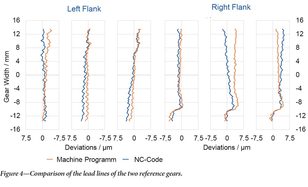
To validate the functionality and accuracy of the converter concerning the transmission of the kinematics, two reference gears were manufactured. The first reference component was manufactured without modifications. The kinematics were calculated using the machine control’s dialog program, considering the tool and workpiece parameters, cf. Figure 4. The second reference gear was also manufactured without modifications using kinematics specified by the converter. First, the kinematics were derived simulatively. The discretized time kinematics, which describes the movements of the tool and the workpiece over time, were calculated. These kinematics were then converted to an NC code using the converter. The two reference gears were measured for their IT quality and examined for the precision of the transferred kinematics. In Figure 4, the comparison of the results of the gear measurement for the left and right lead lines of three tooth gaps each, distributed over the circumference of the two reference gears is shown. Comparing the lead lines reveals that the NC code was able to manufacture a gear that is qualitatively equivalent to the gear produced using the skiving machine’s dialogue program. A maximum difference of 𝛥 = 3.6 μm is found between the two reference gears. Based on the available results, it can be concluded that the deviations detected are in the order of magnitude of the usual manufacturing deviations due to the concentricity of the tool and the workpiece. Sufficient agreement can therefore be assumed. Thus, the functionality and accuracy of the converter could be validated.
Manufacturing of Topological Modifications Using Gear Skiving
After successful validation, the converter can be used to produce topological modifications. For this purpose, modifications are created by varying the axis crossing angle Σ, the center distance a, and the twist angle φ.
Variation of the Center Distance
The results of changing the center distance based on a polynomial with degree 4 are shown in Figure 5. The course of the specified polynomial could be applied to both flank sides. However, there are deviations between the specified and the manufactured modification in terms of the amount obtained over the entire width of the tooth.
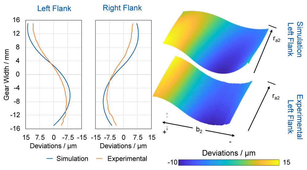
Figure 5—Results of the application of a polynomial degree 4.
On the left flank side, a deviation of 𝛥 = 2.5 µm was detected between the specified and the achieved amount of modification. On the right flank side, this amounts to 𝛥 = 3.4 µm. However, an analysis of the topography of both flank sides reveals a good agreement between the specified course of the modification over the tooth flank and the obtained course of the flank line modification. A high degree of agreement was achieved concerning the course and magnitude of the modifications. The course of the flank lines in the form of a polynomial of degree 4 is clearly recognizable.
The specification of a discontinuous path movement in processes such as generating grinding is used to produce end relief. This procedure could be applied to gear skiving, cf. Figure 6.The desired amount of modification for the left flank in the positive and negative areas of the gear could not be achieved exactly. A difference of 𝛥 = 7.6 µm was determined between the specified modification amount and the amount achieved. Due to the constant center distance setting during cutting in the center of the gear (b2 = 0 mm), no differences resulted between the actual and the nominal values. However, when the center distance is changed to a linear infeed, deviations in the modification amount and the course can be detected.
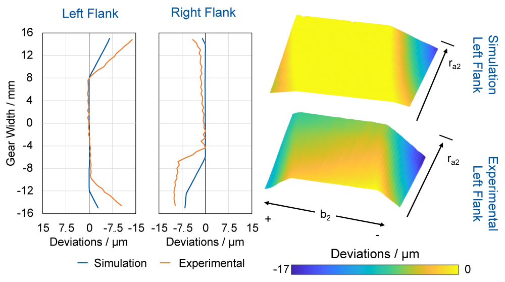
Figure 6—Results of a discontinuous change of the axial distance.
The course of the measured flank line shows that the tool was fed into the workpiece before the desired point for the start of the center distance modification. In the center of the gear (b2 = 8 mm to -8 mm) there are almost no deviations. In radial direction towards the tip radius in the direction of the outer radius, however, deviations between the specification and the manufactured topography become apparent. On the outer sides of the tooth flanks, the change in the center distance to a linear infeed is evident. The start of the linear infeed varies for both flank sides in the radial direction. The deviations at the beginning of the infeed show a linear course along the profile direction of the gear. The shape of the present deviations is similar to a twist, which in principle occurs in modified helical gears (Ref. 14).
Manufacturing of Modifications by Changing the Twist Angle
The twist angle 𝜑 was varied in the range between 0.0° ≤ 𝜑 ≤ 0.2°. A qualitative agreement was achieved between the simulatively defined specification and the actually manufactured flank line concerning the amount and the course, cf. Figure 7. For the left flank side, the largest deviation in terms of amount is identified in the positive area of the tooth width with 𝛥 = 1.0 µm. Due to the two-sided machining, a modification mirrored in amount is obtained for the right flank side. A qualitative agreement was also reached between the specification and the achieved modification. However, deviations can be seen on the right flank in both the positive and negative areas of the tooth width b2, with a difference between the specified and the achieved modification amount of 𝛥 = 4.5 µm. Further deviations on the left flank side become apparent when analyzing the topography. Contrary to the simulation, the amount of modification changes in the profile direction for the manufactured gear. However, it should be noted that a quadratic modification could be applied by adjusting the twist angle 𝜑.
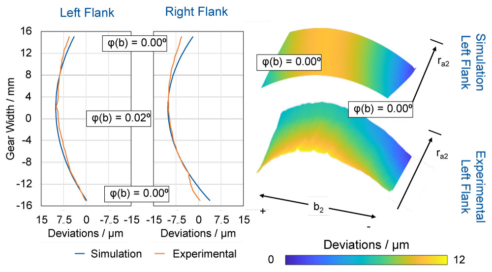
Figure 7—Results of a quadratic change of the twist angle φ.
Manufacturing of Modifications by Adjusting the Axis Crossing Angle
The influence of a variation of the axis crossing angle 𝛴 on the tooth flank topography was investigated in the following. For the investigation, a linear variation of the axis crossing angle 𝛴 was applied along the tooth width b2. The variation of the axis crossing angle 𝛴 was carried out in a range of between -20.02° ≤ 𝛴 ≤ -20.0°. The results are shown in Figure 8 and demonstrate that a specific modification of the tooth flank topography is possible by varying the axis crossing angle. The specified linear variation of the axis crossing angle 𝛴 could not be fully implemented on the left flank. Instead, a parabolic course of the manufactured flank line could be measured. Nevertheless, the specified amount of modification could be maintained, which means that only a maximum difference of 𝛥 = 2.3 µm between the specified and the actual amount was detected. On the right flank side, a linear progression of the measured flank line could be observed. When considering the topography for the left flank side, an analogous picture emerges. Instead of the specified linear course, a quadratic modification of the topography was measured. However, apart from the lack of linearity, an equivalent modification curve is obtained between the simulated and the specified topography. These results show that the specific modification of the tooth flank topography by varying the axis crossing angle 𝛴 is possible. Precise implementation of this technique is challenging and requires further investigation to improve the accuracy of the transferred kinematics.
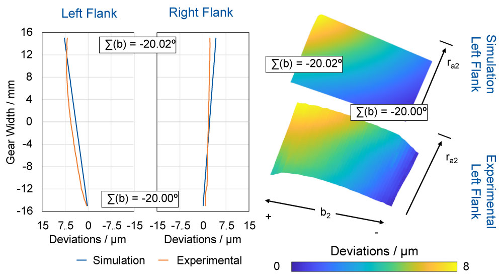
Figure 8—Results of a linear change of the axis crossing angle Σ.
Summary and Outlook
Gear skiving is used for both soft and hard finishing. As a quality critical final step in hard finishing, the process can be used to create modifications to the tooth flank. At present there is no knowledge of the extent to which topological modifications can be applied by gear skiving. In this report, the feasibility of manufacturing topological modifications on an external gear through adapted kinematics for gear skiving has been investigated. The first step was to develop an NC converter. The kinematics derived from a manufacturing simulation had to be transferred to the machine control. Considering the characteristics of the skiving machine, such as the infeed and outfeed paths or the zero offset, the simulated kinematics are converted into NC code that can be executed by the machine controller. A comparison between a gear produced by the dialogue program and a gear produced by the predefined kinematics showed very good agreement between the lead measurements.
The NC converter was used to derive the adapted kinematics for the modifications. The parameters of the center distance a, the axis crossing angle 𝛴, and the twist angle 𝜑 were varied. Due to the two-flank machining, partially offset modifications were generated on the right flank. The specified modifications due to a center distance modification could be kinematically implemented and determined on the tooth flank with small deviations. It was also possible to generate the specification of a discontinuous modification in the form of an end relief. A constant change in the twist angle 𝜑 results in a helix angle deviation fHb. An extension of the adjustment of the twist angle 𝜑 to generate further modifications is therefore a logical conclusion. A quadratic variation of the twist angle 𝜑 led to the generation of a crowning and can therefore be considered as an alternative to the application of a width crowning by changing the axis distance. A linear variation of the axis crossing angle 𝛴 resulted in a parabolic twist, which could be used to compensate for the natural twist caused by lead crowning.
In addition to the derivation of adapted kinematics and the development of a converter, it is necessary to adapt the tool profile to generate topological profile modifications. A realization of the corresponding manufacturing process and thus a superposition of adapted kinematics and tool profile is the next step. An investigation of the transferability to internal gears is also required.
Acknowledgements
The authors gratefully acknowledge financial support from the WZL Gear Research Circle for the achievement of the project results.

Reference
- Brecher, C., Löpenhaus, C., Brimmers, J., 2017. Potential of Free Flank Modifications for Beveloid Gear: International Conference on Gears 2017. International Conference on Gears 2017, Garching, 13–15 September 2017. VDI, Düsseldorf.
- Geiser, H., 2002. Grundlagen zur Beurteilung des Schwingungsverhaltens von Stirnrädern. Diss. Hieronymus, München.
- Griggel, T., 2010. Einfluss von Korrekturen und Fertigungsabweichungen auf die Schwingungsanregung von Stirnrädern. Diss., München.
- Brimmers, J., 2020. Funktionsorientierte Auslegung topologischer Zahnflankenmodifikationen für Beveloidverzahnungen. Diss., Aachen.
- Kohn, B., Utakapan, T., Fromberger, M., Otto, M., Stahl, K., 2017. Flank modifications for optimal excitation behaviour. Forsch Ingenieurwes, Vol. 81, No. 2–3), pp. 65–71.
- Ahmad, M., Löpenhaus, C., Brecher, C., 2017. Analysis of the Dynamic Excitation Behavior of High-Speed Transmissions: Brecher, C. (Ed.), 7th WZL Gear Conference in the USA 2017. July 18–19, 2017. Apprimus Verlag, Aachen.
- Bausch, T., 2006. Innovative Zahnradfertigung: Verfahren, Maschinen und Werkzeuge zur kostengünstigen Herstellung von Stirnrädern mit hoher Qualität, 3rd ed. Expert, Renningen.
- Bauer, R., 2018. Modellbasierte Auslegung von Mehrschnittstrategien beim Wälzschälen. Diss., Chemnitz.
- Zheng, F., Zhang, M., Zhang, W., Guo, X., 2018. Research on the Tooth Modification in Gear Skiving. J. Mech. Des, Vol. 140 , No. 8, p. 74.
- Niemann, G., Winter, H., 2003. Maschinenelemente: Band 2: Getriebe allgemein, Zahnradgetriebe–Grundlagen, Stirnradgetriebe, 2nd ed. Springer, Berlin.
- Norm, 2012. Zahnräder. Zylinderräder und Zylinderradpaare mit Evolventenverzahnung. Bestimmungsgrößen und Geometrie. Beuth, Berlin.
- Radev, S., 2007. Einfluss von Flankenkorrekturen auf das Anregungsverhalten gerad- und schrägverzahnter Stirnradpaarungen. Diss., München.
- Schäfer, J., 2008. Erweiterung des Linienkontaktmodells für die Finite-Elemente-basierte Zahnkontaktanalyse von Stirnradverzahnungen. Diss., Aachen.
- Klocke, F., Brecher, C., 2017. Zahnrad–und Getriebetechnik: Auslegung–Herstellung–Untersuchung–Simulation, 1st ed. Hanser, München, XVI, 668 Seiten.
- Felten, K., 2012. Verzahntechnik: Das aktuelle Grundwissen über Herstellung und Prüfung von Zahnrädern, 3rd ed. Expert, Renningen.
- Linke, H., 2010. Stirnradverzahnung: Berechnung–Werkstoffe–Fertigung, 2nd ed. Hanser, München.
This paper was first presented at the 17th CIRP Conference on Intelligent Computation in Manufacturing Engineering, 12–14 July 2023, Gulf of Naples, Italy. |
