Design Principles of Bevel Gears: Rationale for Zero Sum Profile Shifts and Generating Gear Choices
Bevel gears are typically designed with a zero sum of profile shifts, meaning that the amount of pinion profile shift is equal and opposed in sign to that of the wheel (Ref. 1). This design constraint stands in contrast to cylindrical gears, which often feature independently adjusted profile shifts to optimize performance parameters such as load capacity and center distance. Despite this apparent limitation, the practice of maintaining a zero sum of profile shifts in bevel gears is well-founded. In the following sections, this article will demonstrate why such an approach is both practical and beneficial for bevel gear design.
In bevel gear technology, the planar generating gear serves as the counterpart to the generating rack used in cylindrical gears. However, in practical applications, conical generating gears are often employed instead. This practice is also well-founded, and its rationale will be illustrated through a detailed example.
Bevel Gear Generation
Figure 1 shows an example of a bevel gearset with the number of teeth z1 = 9 and z2 = 13, a shaft angle R = 90 degrees, a tooth height coefficient h = 0.8, a pressure angle a = 22.5 degrees, and profile shift coefficients x1 = 0.2 and x2 = −0.2. The pitch cones, drawn in black, have angles d1 = 34.695 degrees and d2 = 55.305 degrees (Ref. 2) and roll on each other without sliding.
If profile shift coefficients of x1 = 0.7 and x2 = 0.7 are introduced, the shaft angle Σ must be increased to achieve proper meshing. However, since this angle is fixed, it must first be preliminarily reduced so that after increasing it by applying two positive profile shifts, it ultimately reaches the specified value of 90 degrees. As a result, the pitch cone angles decrease and will no longer be in contact. Using the proprietary bevel gear calculation software at Oktoida, the pitch cone angles for these gearings with double positive profile shifts were calculated to be d1 = 31.534 degrees and d2 = 49.267 degrees, and are illustrated in pink in Figure 1. Additionally, tooth thickness must be adjusted to enable proper meshing, since those defined on the decreased pitch cones no longer apply due to the lack of rolling contact between these cones.
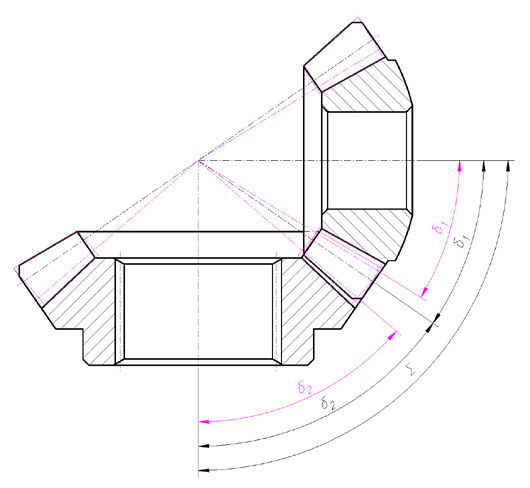
Figure 2 illustrates the original pinion, with a profile shift coefficient of x1 = 0.2, meshing with its planar generating gear (depicted in black). It also shows the pinion with a reduced pitch cone angle and a profile shift coefficient of x1 = 0.7, along with its planar generating gear (depicted in pink). Note that in the latter case, the rolling radius r1 has decreased while the generating gear radius r0 remains unchanged, resulting in a change in the generating ratio i = r1/r0. This effect is even clearer in Figure 5, where, in the shown kinematic setup of the generating process, only the value of this generating ratio has changed. Consequently, due to the change in the pitch cone angle, the generating motion is modified, causing changes in the generated profile angle (Ref. 1).

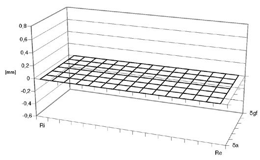
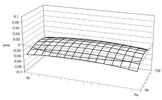
Using the same software, the octoid geometry of the original gear tooth flank was calculated in the form of a point cloud with corresponding normal vectors. This cloud extends from the heel (Re) to the toe (Ri) and from the outer cone (da) to the start of the generated profile at the root (dgf) and will serve as the baseline (zero geometry) for comparisons with geometries obtained through subsequent modifications. Next, in the same manner, the tooth flank geometry of the gear with a reduced pitch cone angle was determined. A comparison of these geometries is presented in Figure 3.