Heat treatment decisions for gears are often reduced to a surface hardness number. That shortcut can work for mild duty, but it frequently breaks down when contact fatigue, scuffing risk, shock events, distortion limits, or finishing constraints become dominant. Many late-stage issues trace back to the same pattern: the duty case is incompletely defined, the process window is underestimated, or verification confirms “a number” without proving the full property profile.
This article offers two practical tools for cross-functional reviews and early process alignment. Table 1 links common duty drivers to a shortlist of heat treatment routes, helping teams narrow options quickly and consistently. Table 2 maps each route to a minimum proof-test plan—case/layer depth, hardness gradients, microstructure confirmation, geometry stability checks, and surface integrity checks when hard finishing is involved. Used together, these matrices connect design intent to measurable evidence and inspection gates, reducing rework and late-stage surprises.
Define the Duty Case First
You do not need a perfect model to make a better selection. You need a shared duty description that captures the dominant drivers.
A practical method is to label each as Low/Medium/High, then pick the top two or three “non-negotiable” drivers. Those drivers determine the route shortlist.
This section summarizes common routes used in gear manufacturing. The focus is not on marketing claims, but on what each route tends to deliver and what must be proven.
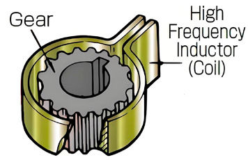
Induction (Surface) Hardening
Best at: Localized hard surface with a tougher core; efficient flow for many parts; can support distortion control when implemented well.
Where it fits: Moderate to high duty parts where selective hardening is practical and cycle time matters.
Verification emphasis: Hardness mapping and depth checks at the highest-stress regions; distortion checks before/after finishing.
Figure 2—Induction hardens teeth fast with a coil.
Carburizing + Quench + Temper (Case Hardening)
Best at: Strong contact fatigue resistance with a tough core when case depth and gradient match the stress field.
Where it fits: High load, long life, and demanding durability requirements.
Limitations: Distortion scatter; coordination with finishing (stock, correction capacity, and surface integrity risk).
Verification emphasis: Effective case depth and hardness traverse, microstructure confirmation, core hardness, distortion statistics across loads; surface integrity checks after hard finishing when risk is elevated.
Nitriding
Best at: Hard surface with minimal distortion due to lower temperature; attractive for distortion-sensitive components.
[advertisement]
Where it fits: Precision gears or parts where dimensional stability is the dominant constraint; wear/scuffing risk control in certain duty profiles.
Limitations: Typically thinner hardened layer; layer and compound-zone control; core must already be sufficiently strong.
The fastest way to shortlist routes is to identify the dominant duty drivers. Use Table 1 to narrow options, then confirm geometry/process compatibility and build the proof-test plan.
Dominant Driver / Constraint
Induction
Carburize + Quench
Nitriding
Q&T
Normalizing
High contact stress, long life (pitting resistance)
C
R
C
A
A
High shock / bending-root robustness
C
R
C
C
A
High-speed sensitivity to small deviations
C
C→R (with finishing)
R
C
A
High scuffing risk (boundary lubrication events)
C
C
R
A
A
Distortion-sensitive geometry / tight fit
R
C
R
R
C
Limited post-heat-treat finishing margin
C
A→C
R
R
C
Selective hardening needed (local zones)
R
A
C
A
A
Short lead-time / flexible routing
R
C
C
R
C
Table 1—Simplified route selection matrix. Legend: R = Recommended; C = Conditional; and A = Generally Avoid.
Verification Matrix (Route → Proof Tests)
Route selection should come with a verification plan that proves the assumptions the design relies on—especially for case-based routes.
Route
Key Assumption to Prove
Typical Evidence Set (select per risk)
Induction
Hardened pattern covers critical zones; uniformity is stable
hardness range; microstructure; dimensional stability before subsequent hardening
Table 2—Verification Plan Matrix (Typical Minimum Evidence).
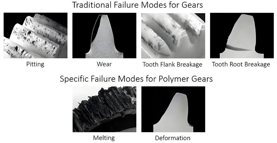
Figure 4—Typical gear damage patterns and failure appearances at a glance.
Representative Duty Profiles
The same route can succeed or fail depending on which constraints dominate. The examples below illustrate how the matrix approach works.
Agricultural Machinery Drives
Typical traits: long service hours, contamination exposure, seasonal shock events, durability-first.
Route tendencies: carburizing for primary torque paths; induction for selective needs and robust cores where appropriate.
Proof-test focus: case-depth strategy or pattern coverage; distortion control plan; cleanliness and lubrication assumptions documented.
Heavy Truck Power Transmission
Typical traits: high torque, long mileage, repeated duty cycles, strict repeatability requirements.
Route tendencies: carburizing for high-load gearsets with hard finishing; nitriding for distortion-sensitive precision parts where the layer matches the duty case.
Proof-test focus: hardness traverse and depth evidence; distortion statistics; post-finish surface integrity risk control when grinding is aggressive.
Route tendencies: carburizing for heavily loaded stages; induction for large components and selective hardening cases; Q&T for modest-duty gears with appropriate design margins.
Typical traits: high rpm and continuous duty where small geometry variation becomes more noticeable; stable finishing and distortion control are often decisive.
Route tendencies: carburizing paired with controlled finishing; nitriding where dimensional stability dominates and the layer fits the duty assumptions.
Proof-test focus: geometry stability pre/post, consistent finishing output, and verification that the achieved layer/case matches the design model.
Failure Modes and Evidence Chains (Fast Troubleshooting)
When a program experiences early failures or fit problems, the fastest path is symptom → evidence → correction.
Pitting / Spalling
Symptom: pits growing into spalls on active flanks.
Evidence: duty severity review; case depth/gradient vs stress region; surface condition and cleanliness.
Corrections: revise duty assumptions; adjust case strategy or route; improve finishing/lubrication/cleanliness controls.
Scuffing (Adhesive Wear)
Symptom: smeared or torn surfaces, rapid damage progression under boundary lubrication.
Evidence: duty temperature and lubrication regime; surface condition; contact pattern and alignment checks.
Corrections: raise scuffing margin via lubrication/cleanliness/finish strategy; reconsider route if scuffing is dominant.
Tooth Fracture
Symptom: fracture often originating at root under shock.
Evidence: shock classification; core microstructure/hardness; stress raisers and origin analysis.
Corrections: ensure core robustness matches duty; stabilize process; adjust design margins or route as needed.
Fit or Assembly Problems After Heat Treat
Symptom: parts do not assemble or require excessive correction.
Evidence: geometry measurements pre/post; distortion scatter across loads; stock allowance vs correction capability.
Corrections: distortion control plan, fixturing/quench strategy, gating inspections, and finishing alignment.
Distortion and Finishing: The Hidden Coupling
Even an appropriate route can fail without an aligned distortion and finishing plan.
Practical Actions
Identify distortion-sensitive features early (runout, fit bores, tooth deviations).
Shortlist routes using Table 1; eliminate A for non-negotiables.
Confirm geometry/process compatibility and finishing capacity.
Build proof tests using Table 2; prove case/layer assumptions.
Add distortion gates and acceptance limits.
If hard finishing is used, plan surface integrity risk controls.
Link failure modes to evidence chains before production ramp.
Lock process settings and traceability to reduce scatter.
Update matrices as capability data accumulates.
Conclusion
A robust gear heat treatment decision is not a single process choice. It is a matched set of duty assumptions, route capability, finishing constraints, and proof tests. The duty-to-route matrix helps shortlist workable options early, but the decision only becomes reliable when the verification plan proves the key assumptions with measurable evidence—such as case/layer depth, hardness gradients, microstructure confirmation, and post-heat-treat geometry stability.
Most late-stage surprises—premature surface distress, tooth fracture under shock, or fit and assembly issues—can be traced to an incomplete duty description, an underestimated distortion/finishing window, or verification that checks “a number” without confirming the full property profile.