[advertisement]
Ask the Expert

March 4, 2026

Brian Dengel


Ask the Expert

Gear Selection

Question: In your experience helping engineers select power transmission components, what is the most misunderstood concept in gear selection, and how would you explain it to a young engineer?

Brian Dengel

Expert response provided by Brian Dengel, General Manager, KHK USA Inc.

Entry-level engineers are at a disadvantage when selecting power transmission components due to their lack of education and experience. While attending an ABET-accredited engineering school, most students are only exposed to gearing during a single lecture in a course titled Mechatronic Design, which is just one course over their entire educational journey. If they participate in a Senior Project in Mechanical Engineering, they might need to draw on the basics covered in that single lecture. Beyond these two opportunities, recent graduates have next to zero knowledge of gearing.

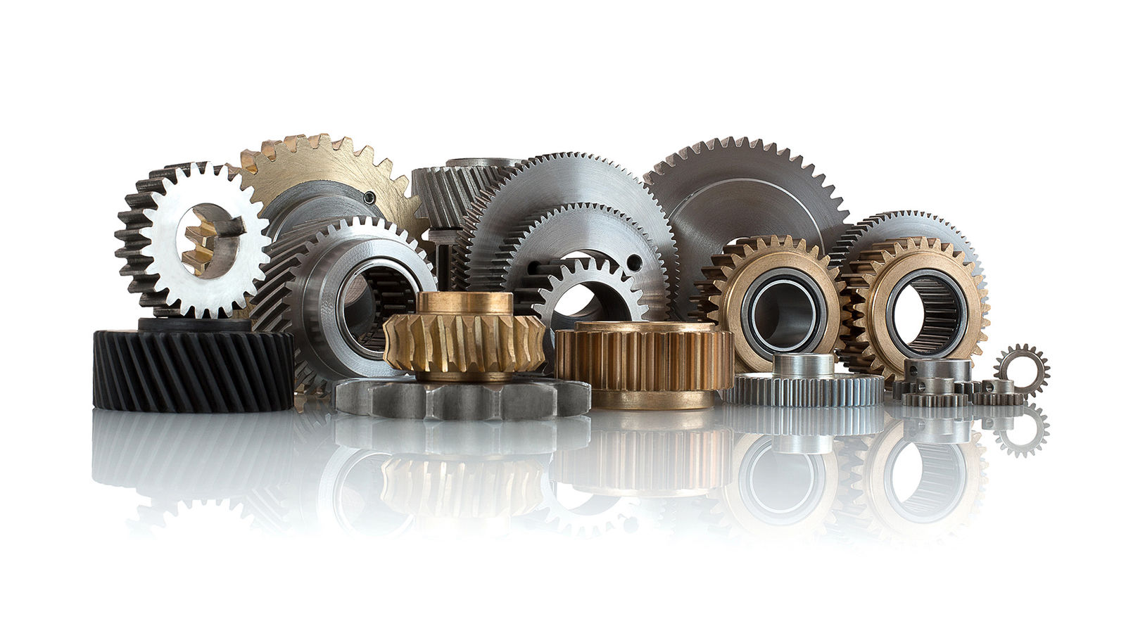
When designing a gear system, there are various parameters that need to be considered. Many of the parameters are driven by the desired output of the gearing, and others are determined by the laws of geometry and physics. Choosing the proper gear based on these factors is critical to ensuring a reliable gear system.

The most misunderstood concept in gear selection is that the parameter of the size of the gear is not independent but dependent on other parameters, including the operating environment, the material makeup of the gear, the applied loading, the operating speed, and the design life.

The first consideration that will drive the size of the gear is the environment in which it will operate. Is the gear going to operate inside an enclosure, or will it be exposed? Will it be used in an industrial environment, or a temperature-controlled environment, or will it be exposed to food, rain, dust, or the sun? If the gear is going to be inside an enclosure, then the size of the gear is limited to the interior size of the enclosure. Open gearing does not have this limitation.

These 24-tooth gears in Modules 1.5, 2.5, 3, and 4 demonstrate how pitch selection—not tooth count—drives gear size, with coarser pitches enabling higher torque capacity at the cost of a larger footprint.

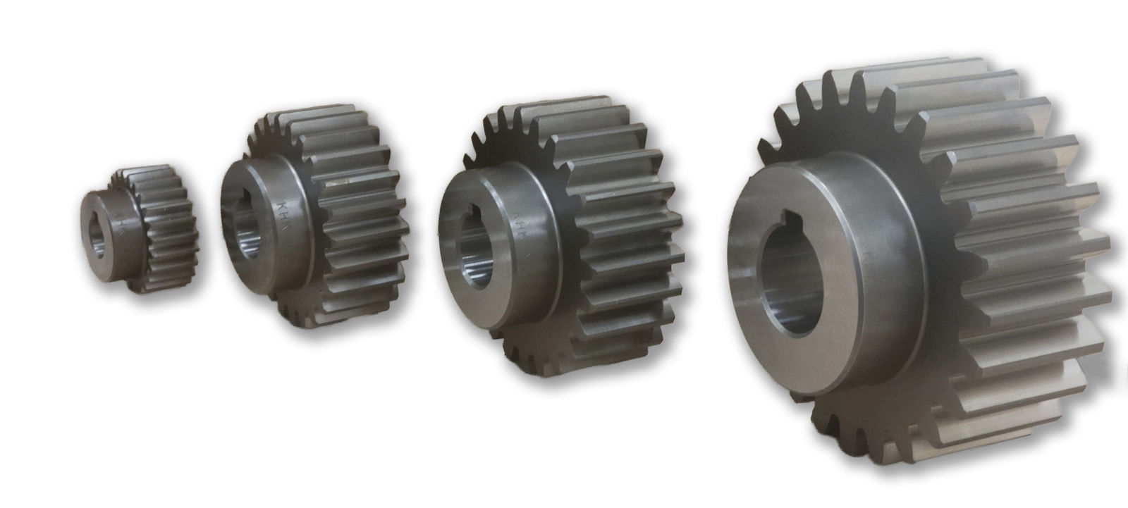
The second consideration that will affect the size of the gear is the material. Does the gear need to be lightweight, or does it need to manage significant impact loads? Does the gear need to be washed down, or does it need to be nonmagnetic? Each of these considerations will lead to a different material choice. Lightweight gearing might be produced from aluminum or plastic. Gears in food environments that need to be washed down or gears that need to be non-magnetic will need to be produced from stainless steel. Gearing that is managing large loads most likely needs to be produced from alloy steel. As steel is three times stronger than aluminum and six times stronger than nylon, a gear made from steel can be one-third the size of an aluminum gear or one-sixth the size of a nylon gear and carry a similar load.

Share and save:


This article appeared in the January/February 2026 issue.


Read PDF

[advertisement]

The other considerations that affect the size of a gear are the applied load, the operating speed, and the desired design life. As these three parameters are interconnected, the gear design will change proportionally as each is evaluated. The operating speed of a gear is dependent only on the input speed if it is the driver, and it is dependent on the speed ratio of the gear pair when it is the driven. The maximum allowable bending strength is dependent on the size of the gear, the applied load, and the desired design life. Since torque and speed are inversely proportional, a gear running at a speed of more than 10,000 rpm can only manage a small amount of torque, whereas a gear running at one rpm can withstand a much higher torque. If the design life is measured in minutes of continuous use, instead of months, then the maximum allowable torque due to surface failure can also be increased.

The final consideration for the size of a gear is the pitch. The pitch of a gear drives the formulas for size. A coarse pitch gear, such as a Module 4 spur gear with twenty-five teeth, will have a pitch diameter of 100mm and typically a face width of 40 mm. However, a medium pitch gear, such as a Module 1.5 spur gear with twenty-five teeth, will have a pitch diameter of 37.5 mm and typically a face width of 15 mm. If we normalize these two gears with both having a face width of 15 mm and both made from carbon steel with a design life of 40 weeks operating 40 hours per week, the Module 1.5 gear would have a maximum allowable bending strength torque of 26.7 Nm, but the Module 4 gear would have a maximum allowable bending strength of 189.8 Nm. These values show that the tooth size affects the load capacity when all other parameters are equal. However, the larger module gear has a significantly larger pitch diameter, which may not be suitable for the application.

Each of these parameters has an impact on the proper size for a gear that is best for the application. Young engineers need to understand that the size of a gear is an outcome of the needs of the application and not predetermined by the desire for the gear to be a particular size.

These 24-tooth gears in Modules 1.5, 2.5, 3, and 4 demonstrate how pitch selection—not tooth count—drives gear size, with coarser pitches enabling higher torque capacity at the cost of a larger footprint.