[advertisement]
Feature Articles

April 16, 2026

Dr. Antoine Turich


Features

Profile Grinding of Large Gears

Increasing material removal efficiency through advanced infeed strategies

(All images: Gleason Corporation)

Profile grinding is the hard-finishing process of choice for large gears with demanding requirements regarding load transmission, running smoothness, and complex tooth modifications. No other hard-finishing process offers a comparable level of flexibility across such a wide range of applications. Profile grinding can be applied to very small as well as very large gears, to external and internal gearing, to involute and non-involute tooth forms, to components with and without interfering contours, and to both simple and highly complex tooth modifications. Furthermore, profile grinding allows the achievement of excellent quality levels that cannot be attained by any other hard-finishing process over this broad application range.

Traditionally, the only disadvantage attributed to profile grinding has been its productivity. As a single-tooth-gap process, it is associated with higher nonproductive idle times compared with continuously generating processes. Through consistent further development of both process technology and machine design, however, this perceived disadvantage has been largely eliminated. This article presents examples illustrating how material removal efficiency during profile grinding can be significantly increased by optimizing the infeed strategy.

Conventional Infeed Strategy

When non-grinding time is discussed, attention is often limited to unproductive machine and workpiece movements between individual tooth gaps. However, the machining of each tooth gap itself already offers considerable optimization potential. To identify this potential, it is necessary to first understand the traditional infeed strategy that is still commonly applied in profile grinding.

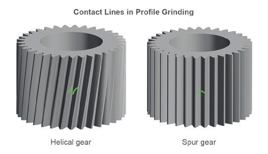
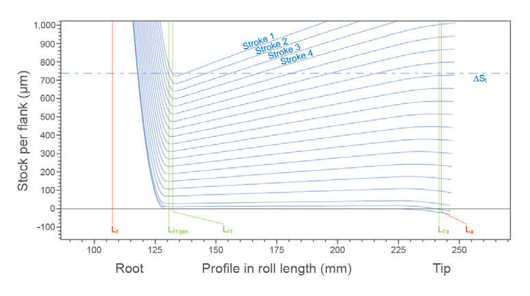
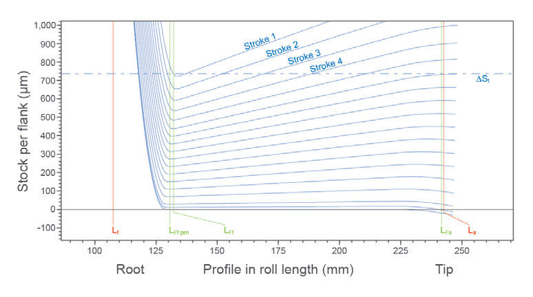
In conventional profile grinding, the total stock to be removed—including heat treatment distortion—is typically removed successively in multiple grinding strokes or passes. The grinding wheel is dressed to the final tooth gap geometry, including any specified profile modifications. Due to the remaining stock, however, the grinding wheel does not initially fit into the tooth gap. As illustrated in Figure 1 (left side), contact occurs only in the lower profile region near the tooth root.

Figure 1—Contact conditions using a conventional infeed strategy.

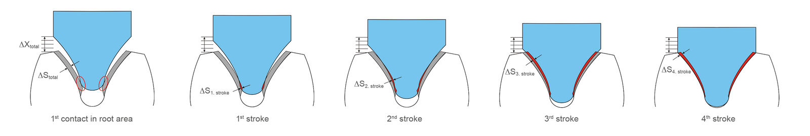
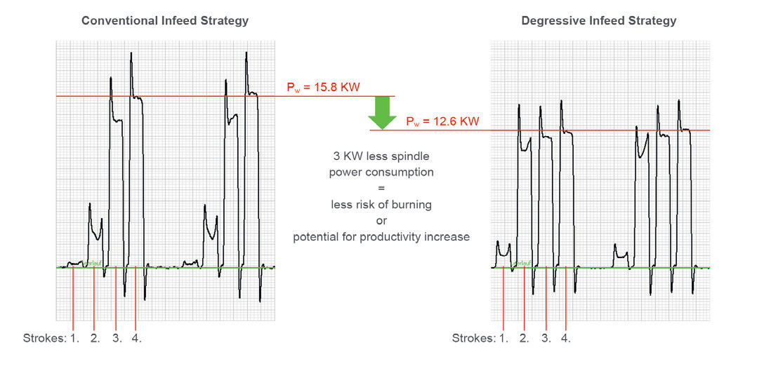
If the same radial infeed is applied in each grinding stroke, material removal during the first strokes is very limited and concentrated primarily in the lower portion of the tooth profile toward the root. Full contact along the entire tooth profile is achieved only in later strokes (in the example shown, starting with the third of four strokes). Consequently, the full material removal potential of the process is not utilized from the beginning but only during subsequent strokes. The initial strokes are therefore highly inefficient, even though the same infeed values and feed rates are applied as in all other strokes. This inefficiency can be clearly observed by analyzing the spindle power used during grinding (Figure 2, left side).

Figure 2—Spindle power consumption conventional infeed strategy versus degressive infeed strategy.
Share and save:


This article appeared in the March/April 2026 issue.


Read PDF

[advertisement]

In the example shown, the first two of four grinding strokes require only very low spindle power, reflecting the extremely low material removal rate in these strokes. Only during the third and fourth strokes does spindle power reach the level corresponding to the defined process parameters. A noteworthy detail is that the highest spindle power of 15.8 kW occurs in the final stroke. In addition, this infeed strategy results in uneven loading of the grinding wheel along the tooth profile, which can lead to premature and unevenly distributed wheel wear.

The described effect of inefficient and uneven material removal occurs on all machines using a conventional infeed strategy, which is still common practice in many applications. For gears with low tooth numbers, the curvature of the involute profile is more pronounced, further intensifying this effect.

Degressive Infeed Strategies as Starting Point for Optimization

Uneven material removal associated with the conventional infeed strategy can be partially compensated for by using a degressive infeed strategy. In this case, larger radial infeed is applied in the initial strokes, followed by smaller infeed in the later strokes. The effect of this strategy can again be clearly seen by evaluating spindle power demand (Figure 2, right side).

Although full contact along the entire tooth profile is still not achieved in the first stroke, the subsequent strokes show significantly higher and more evenly distributed spindle power levels. In addition, the maximum spindle power required (12.6 kW) is approximately 3 kW lower than with the conventional strategy, even though the same gear geometry is ground. This reduction in maximum spindle power corresponds either to a lower risk of grinding burn or to additional potential for increasing feed rates and thus productivity.

While the degressive infeed strategy reduces inefficiencies within the grinding cycle, it still does not provide full utilization of the material removal potential in the early strokes.

A(X) Technology: Ensuring Optimal Contact Conditions

To achieve maximum material-removal efficiency in nearly all grinding strokes, a further infeed strategy, referred to as A(X), was developed by Gleason. This patented technology uses an additional adjustable parameter critical to profile grinding: the swivel angle of the grinding wheel relative to the gear. This angle does not necessarily have to correspond to the helix angle (β) of the workpiece.

Different swivel angle settings are commonly used in practice, depending on the intended objective. While the contact line between the grinding wheel and a tooth gap of a spur gear (β = 0) lies in a single plane—the axial plane—this contact line is spatially distributed along the tooth flank in helical gears (β ≠ 0) (Figure 3).

Figure 3—Contact lines in profile grinding.

The contact line, therefore, extends axially along the tooth gap on both the left and right flanks. The start position, end position, and axial length of the contact lines on the two flanks can be strongly influenced by the selected swivel angle. Each swivel angle variant requires an individually calculated and dressed grinding wheel profile.

In conventional double-flank profile grinding, the swivel angle is often selected such that the contact lines on the left and right flanks are located at the same axial position. This ensures that the grinding wheel engages and disengages both flanks simultaneously during a grinding stroke, preventing undesired entry and exit effects caused by grinding-force-induced flank deflection. Such effects often appear in measurement as unwanted flank-line deviations at the beginning and end of the contact zone.

Other swivel-angle variants are used, for example, to minimize the axial extension of the contact line, thereby largely avoiding bias/twist effects during single-flank grinding. Additional swivel angle settings can be applied to achieve balanced peak positions of flank line crowning (cβ) on the left and right flanks.

[advertisement]

With the A(X) infeed strategy, the swivel angle of the grinding wheel varies from stroke to stroke without changing the grinding wheel profile. The grinding wheel is dressed for the swivel angle effective in the final stroke and remains unchanged throughout the entire grinding process. By adjusting the swivel angle for each grinding stroke, the contact line between the grinding wheel and the tooth-gap geometry in that stroke conforms optimally to the profile.

As a result, near-full contact along the entire tooth profile is achieved in almost every stroke, with the contact line running nearly equidistant to the tooth profile. Material removal per stroke is therefore uniform along the profile and consistent across all strokes. In contrast to conventional and degressive strategies, the grinding wheel is no longer subjected to localized loading but is instead loaded evenly over the entire profile. This uniform and highly effective material removal allows the total stock to be removed in fewer grinding strokes, resulting in a significant reduction in cycle time with reduced process risk, such as thermal damage, so-called grinding burn. The designation A(X) reflects the underlying mathematical relationship, in which the swivel angle (A-axis) is adjusted as a function of the radial infeed (X-axis).

Application Example: Planetary Gear for Wind Turbine Gearboxes

The effectiveness of the degressive infeed strategy and A(X) infeed strategy is demonstrated using a practical application example of a planetary gear typical for modern wind turbine gearboxes. The gear parameters were as follows: number of teeth (z) = 33, module (m) = 24 mm, helix angle (β) = 8.1 degrees, pressure angle (α) = 20 degrees, tip diameter (da) = 894 mm, and face width (b) = 600 mm. The assumed tooth flank stock, including heat-treatment distortion, was 0.7 mm.

Using the conventional infeed strategy as a reference, the stock was removed using 17 roughing strokes and two finishing strokes, resulting in a total cycle time of 82 minutes. With the degressive infeed strategy, two roughing strokes could be eliminated, reducing cycle time to 78 minutes (−5 percent). By applying the A(X) infeed strategy, the number of roughing strokes was reduced to 11, resulting in a total cycle time of 65 minutes and a cycle time reduction of 21 percent.

 conventionaldegressiveA(X)
Roughing strokes171511
Finishing strokes222
Total strokes191713
    
Total cycle time [min]827865
Cycle time improvement -5%-21%

Table 1—Comparison of different infeed strategies.

Figures 4 to 6 show the actual material removal per stroke for the different variants, with the tooth flank allowance in µm plotted on the vertical axis and the tooth profile plotted as roll length on the horizontal axis from the root (Lf) (left) to the tooth tip (La) (right). Analysis of the material removal per stroke shows that the conventional strategy requires seven strokes before full contact along the entire tooth profile is achieved. With the degressive strategy (Figure 5), full contact occurs after five strokes, while with the A(X) infeed strategy (Figure 6), full contact is achieved starting with the second stroke. The diagrams further illustrate how closely the grinding wheel profile conforms to the tooth gap geometry when using the A(X) infeed strategy, as indicated by nearly parallel material removal curves across successive strokes.

Figure 4—Material removal for all passes with a conventional infeed strategy.
Figure 5—Material removal for all passes with a degressive infeed strategy.
Figure 6—Material removal for all passes with the A(X) infeed strategy.

In all three strategies, the maximum material removal measured perpendicular to the tooth flank is identical. This indicates that the significantly shorter cycle time achieved with the A(X) infeed strategy does not increase the risk of grinding burn.

The A(X) infeed strategy is available with many other technological functions, such as smart dressing, wobble and eccentricity compensation, and twist-controlled double-flank grinding to maximize efficiency, productivity, and gear quality. These functions are implemented on all high-precision Gleason profile grinding machines, covering gear sizes up to 6,000 mm in workpiece diameter.

Figure 7—All Gleason profile grinding machines up to 6,000 mm in workpiece diameter feature the A(X) infeed-strategy software.

Conclusion

By combining advanced infeed strategies with modern machine technology, the traditional productivity limitations of profile grinding can be largely overcome. While degressive infeed strategies already reduce inefficiencies, the A(X) infeed strategy enables near-constant contact conditions and uniform material removal throughout the grinding cycle. This results in substantial cycle time reductions without compromising quality or process stability, making profile grinding a highly competitive hard-finishing process for large, high-performance gears.

gleason.com

[advertisement]