[advertisement]
Feature Articles

June 12, 2026


Features

Systems Failure

Rethinking failure, replacement, and supply
strategy in heavy industry

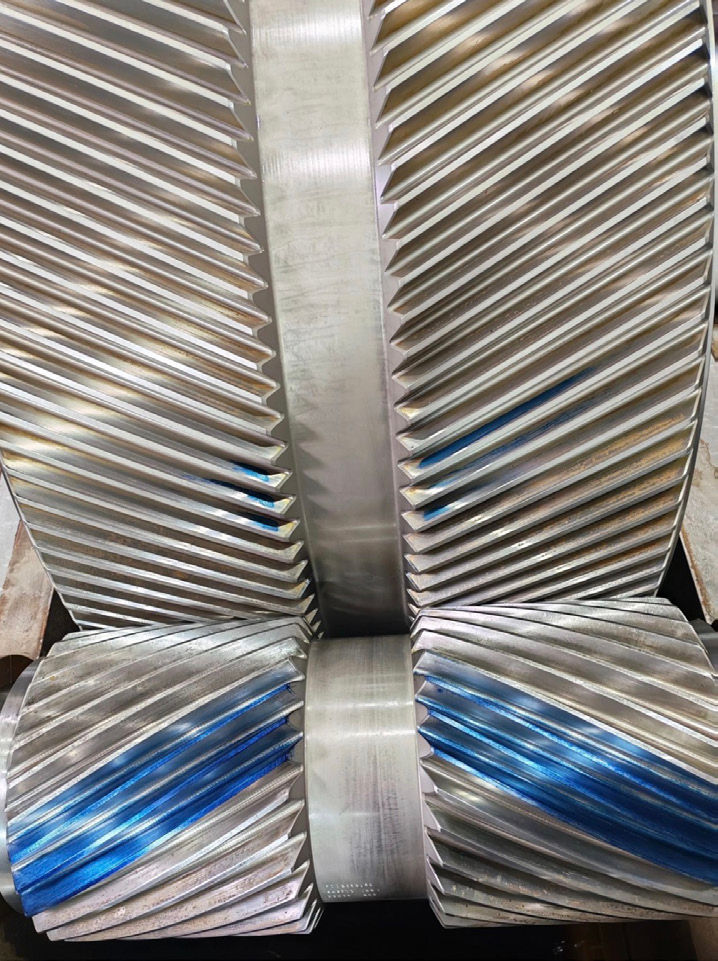
Figure 1—Early-stage surface fatigue and distress on a heavy-duty gear tooth flank. Surface damage may progress well before catastrophic failure becomes visible. (All Images: Pamilanga Ltd.)

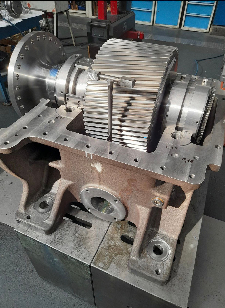
In heavy industry, gears rarely fail in the dramatic way people imagine. More often, there is no broken tooth, no immediate seizure, and no single event that clearly marks the beginning of the problem. What appears to be a healthy gear may already be operating with edge loading, unstable lubrication film, progressive surface fatigue, or overload at the tooth root. By the time visible damage becomes obvious, the failure mechanism has usually been active for some time. This matters because plant decisions are still too often made at the component level. A gear is inspected, damage is found, and attention immediately shifts to material quality or OEM replacement. In practice, however, most serious gear incidents are system-driven. Alignment condition, shaft and housing stiffness, bearing clearance, lubrication regime, thermal growth, start-stop duty, shock loading, and maintenance response all influence the way the tooth pair actually carries load. Understanding that distinction changes not only how failures are diagnosed, but also how replacement strategy should be managed. Once a critical gear is out of service, the challenge is no longer purely technical. The question becomes how to restore reliability quickly, with controlled risk, and without accepting unnecessary dependence on long OEM lead times.

Failure Often Starts Long Before Fracture

Early-stage gear distress is typically progressive rather than catastrophic. Micropitting is one of the clearest examples. Under mixed or boundary lubrication, local asperity contact causes repeated surface fatigue at a very small scale. The damage may first appear as a dull grey patching effect on the active flank, usually near the pitch line or in areas where contact has shifted away from the intended load zone. Operators may continue running because the gear still looks serviceable and the machine has not yet tripped. But once the surface is disturbed, local stress concentration increases and the damaged area tends to grow.

Figure 2 — Contact pattern verification on helical gear teeth. Blue marking compound highlights the actual contact area across the tooth flank. Uneven patterns may indicate edge loading, alignment deviation, or load distribution issues before visible gear damage occurs.
Figure 2 — Contact pattern verification on helical gear teeth. Blue marking compound highlightsthe actual contact area across the tooth flank. Uneven patterns may indicate edge loading,alignment deviation, or load distribution issues before visible gear damage occurs.

Scuffing is different in appearance and mechanism. It is associated with lubricant film collapse combined with sliding under load, often during transient events such as hot restarts, contamination, high bulk oil temperature, or inadequate viscosity at operating conditions. Instead of fine fatigue damage, the tooth shows tearing, smearing, and directional scoring. Bending fatigue, by contrast, develops from repeated tensile stress at the tooth root. If the effective load distribution across the face width is poor, root stress rises sharply at one side, and cracks may initiate from the fillet long before a full tooth breakage occurs.

The key lesson is that visible damage type is only the surface expression of the real operating condition. A gearset may show micropitting because the lambda ratio is too low for the actual duty, because the contact pattern has moved toward one edge, or because load spikes are repeatedly pushing the pair beyond its intended regime. A correct diagnosis, therefore, requires the gear to be viewed as part of a dynamic system, not as an isolated manufactured part.

Failure modeWhat it looks like in serviceWhat usually drives it
MicropittingGrey frosting, matte patches, early surface fatigue on active flankLow film thickness, edge loading, roughness mismatch, contamination, repeated load cycling
ScuffingSmearing, tearing, directional score marks, rapid local distressLubricant film collapse, high sliding, temperature excursion, poor viscosity control
Macropitting / spallingLarger pits or flake-like surface removalProgressed surface fatigue, overload, inadequate hardness or case support, misalignment
Bending fatigueRoot crack initiation, tooth fracture after repeated cyclesHigh root stress, poor load distribution, overload events, fillet stress concentration

Table 1—Typical failure modes and what they usually indicate.

Material Is Often Blamed First

Share and save:


This article appeared in the June 2026 issue.


Read PDF

[advertisement]

Material quality and heat treatment certainly matter. Case depth, flank hardness, core strength, cleanliness, grinding burn, residual stress, and geometry quality all affect life. But in field investigations, these factors are often blamed too early because they are easier to discuss than system behavior. A replacement gear can be metallurgically sound and still fail early if the real problem lies in the way load reaches the teeth.

Misalignment is the most common hidden amplifier. It does not have to be dramatic to be damaging. A contact pattern that migrates toward one side of the face width creates local overload, changes the oil film behavior, and raises tooth root stress. The source may be shaft deflection under torque, pedestal movement, bearing wear, housing distortion, soft foundation response, assembly error, or thermal growth between cold alignment and hot operating conditions. In large mill drives and heavily loaded reducer stages, this distinction is critical: the measured alignment at standstill may not represent the alignment under process load.

Lubrication must also be treated as a system variable rather than a maintenance checkbox. Oil cleanliness, viscosity selection, additive chemistry, temperature stability, spray pattern or bath level, and actual flow to the mesh all matter. Technically correct oil can still perform poorly if contamination rises, the nozzles miss the mesh, or operating temperature drives viscosity below the intended range. When film thickness falls, the tooth surface begins sharing load through direct asperity contact, and fatigue accelerates.

This is why experienced investigators usually ask four questions before discussing replacement: What is the actual contact pattern under load? What changed in the machine before the damage was noticed? What do oil condition and vibration trends show? And has the train been checked as an assembled system rather than as a collection of separate parts?

Fine Grinding Circuits—Wear, Efficiency, and the Wrong Simplifications

A similar pattern appears in fine grinding circuit decisions. In mineral processing discussions, equipment selection is often reduced to a simple efficiency comparison between ball mills and vertical grinding technologies. In reality, the decision is again system-dependent. Ball mills are sometimes dismissed as old technology, yet they remain highly effective where robust operation, predictable particle-size control, and tolerance to variable feed are more important than headline energy claims.

In abrasive services such as silica-rich duty, wear behavior becomes a central design variable. Vertical configurations can offer attractive energy performance, but the wear environment on rollers, tables, or other grinding surfaces may become the limiting factor in practice if the ore or industrial mineral is highly abrasive. Ball mill circuits paired with appropriate classification, liner selection, and media strategy often remain the preferred solution where product fineness must be controlled reliably, and wear risk has to be managed conservatively.

The point is not that one machine type is universally superior. It is that equipment should be selected according to the real operating constraint: energy, wear, maintenance interval, product-size distribution stability, or project execution risk. Just as with gears, the best engineering decision emerges when the component is evaluated in the context of the full duty.

What a Practical Field Assessment Should Include

A useful field assessment does not begin and end with photographs of damaged teeth. It should combine surface observation, geometry checks, operating evidence, and surrounding machine condition. On the tooth flanks, inspectors should review the active contact pattern, the position and direction of distress, the extent of end loading, and whether wear is uniform across the set. Backlash values should be recorded rather than estimated, and radial or axial runout should be checked where possible. In repaired or long-running units, wear pattern history can be as informative as a one-time measurement.

Supporting evidence from the machine is equally important. Bearing clearances, shaft journal condition, coupling status, housing fastener security, foundation behavior, and machine base integrity all influence the mesh. Oil should be reviewed not only for contamination and viscosity but also for wear debris trend, water ingress, and signs of thermal distress. Vibration data, if available, may show rising gear-mesh activity, sidebands related to modulation, or changes in 1x shaft response that point back to alignment and support condition.

For high-consequence assets, the best investigations convert observations into a decision matrix: continue with monitoring, repair in place, re-machine selected parts, or replace the gearset and correct the surrounding system drivers. That last point is essential. Replacing a gear without addressing the reason it was distressed simply resets the clock.

The Real Operational Problem: Replacement Under Pressure

[advertisement]

Once serious damage is confirmed, plant priorities change immediately. Engineering may still want root-cause certainty, but operations will focus on uptime, production loss, and restart risk. In this phase, OEM dependency becomes a major constraint. For critical gears used in mills, high-load reducers, and heavy-duty transmission systems, original replacement lead times can extend from several months to much longer, depending on size, heat treatment route, pattern availability, and backlog. Even where price is accepted, time may not be.

This is where many organizations face an uncomfortable gap between theoretical preference and practical recovery. Waiting for the original source may be the simplest administrative answer, but it is not always the best risk decision. If the plant is losing production weekly, the true cost of replacement is not only the purchase price of the gear. It is the combined effect of downtime, temporary workarounds, maintenance exposure, and the possibility that the new gear will enter the same operating condition that damaged the previous one.

A better response framework separates two questions that are too often blended together: first, can a replacement be manufactured outside the OEM channel to the required technical standard, and second, what additional checks are necessary to ensure the system does not re-create the same failure mode? Once those questions are separated, alternative sourcing becomes a technical and project-management exercise rather than a compromise.

Alternative Manufacturing Is Viable if Qualification Is Disciplined

Alternative manufacturing should never mean copying a damaged part blindly. The process must begin with disciplined reverse engineering and qualification. First, the gear geometry needs to be captured correctly: module or diametral pitch, pressure angle, helix angle if applicable, face width, tooth count, profile modifications, root geometry, mounting interfaces, and any relevant fit or runout conditions. Three-dimensional scanning can help, but it is not enough by itself. Damaged or worn teeth can distort the digital picture, so direct measurement and interpretation by gear specialists remain essential.

Second, the material and condition of the original part must be understood. Depending on the component, this may include chemistry verification, hardness mapping, case-depth evaluation, microstructure review, and crack inspection. The objective is not simply to identify what the previous gear was made from, but to understand whether that specification was appropriate for the duty. In some cases, the best replacement is a like-for-like reproduction. In others, the better choice is to preserve geometry while improving process control, grinding quality, cleanliness, or heat treatment consistency.

Third, manufacturing route and inspection plan must be aligned with application risk. Blank production method, machining sequence, heat treatment route, flank finishing, balance if relevant, non-destructive testing, and final gear metrology all need to be defined before production begins. A qualified supplier should be able to show not only that it can machine a gear, but also that it can control lead error, profile error, pitch accuracy, hardness, and distortion across the full process. This is particularly important for large gears where heat treatment and final finishing introduce significant variability if not managed closely.

Finally, replacement planning has to include installation and startup discipline. Contact checking, alignment verification, lubrication readiness, controlled commissioning, and early inspection intervals are part of the replacement strategy not an afterthought. A technically correct gear installed into an unchanged misaligned train is still a vulnerable gear.

Figure 3 — Gearbox assembly under inspection. Heavy-duty gear and shaft assembly during fitting and inspection. Long-term reliability depends on evaluating the complete system rather than replacing the gear alone.

Representative Field Case: Heavy-Duty Mill Drive

The following anonymized case reflects a pattern commonly seen in heavy-duty mill drives. A plant identified progressive flank distress on a critical drive gear after operators reported increasing noise during load changes. There was no tooth breakage and no immediate trip event, but inspection showed visible micropitting concentrated away from the intended central contact zone, together with signs of uneven load across the face width. Initial reaction focused on whether the gear material had been inadequate.

A broader review changed the picture. Contact evidence suggested recurring edge loading. Further checks found that bearing condition and support behavior had allowed the mesh to operate differently under process load than during static alignment. Oil condition was serviceable but not ideal, and the combined effect was enough to push the flank into an unfavorable lubrication regime. In other words, the damaged gear was real, but it was also a symptom of a train-level issue.

The plant now faced a familiar problem. OEM replacement would restore the nominal design, but the delivery window was commercially difficult for the operation. An alternative path was evaluated based on full geometry capture, material verification, manufacturing qualification, and a parallel plan to correct alignment behavior during installation. The result was not simply a faster replacement part. It was a controlled recovery package: reproduce the gear to the required standard, verify the support system, restore lubricant delivery, and commission with early inspection points. The important lesson was that the best outcome did not come from choosing between OEM and non-OEM in abstract terms. It came from combining correct manufacturing with a correct understanding of why the first gear became distressed.

StepWhat must be confirmed
Geometry captureTooth form, helix or spur geometry, profile modifications, interfaces, fits, and allowable runout
Material verificationChemistry, hardness, case depth where relevant, microstructure, crack status, and previous distress evidence
Design validationLoad path review, service condition check, and confirmation that the reproduced design suits actual duty
Manufacturing planBlank route, machining, heat treatment, grinding or finishing, and distortion control sequence
Inspection packageGear metrology, NDT, hardness results, dimensional report, and release criteria before shipment
Installation and startupAlignment under realistic condition, contact pattern, lubrication readiness, and controlled run-in or early follow-up inspection

Table 2—Qualification checklist for non-OEM replacement.

Conclusion

In heavy industry, gear damage should rarely be treated as an isolated component problem. What appears on the tooth flank is often only the visible result of a broader system condition shaped by alignment, load distribution, lubrication behavior, structural rigidity, and operating practice. For that reason, the most effective response is not simply to replace the failed part, but to understand why the damage developed, how the surrounding system contributed to it, and what risks remain if the same conditions are left unchanged.

The same logic applies to replacement strategy. OEM supply may remain the preferred path in some cases, but long lead times and operational pressure often require a more flexible and technically disciplined alternative. When reverse engineering, material verification, process control, and inspection are handled correctly, non-OEM replacement can provide a reliable and practical solution without compromising performance.

Ultimately, the strongest engineering decisions come from combining failure understanding with supply strategy. Plants that evaluate gears as part of a working system—rather than as isolated spare parts—are better positioned to reduce downtime, control risk, and recover faster when failures occur.

pamilanga.com

[advertisement]