[advertisement]
Technical Articles

April 16, 2026


Dr. Ing. Volker Heuer


Christof Ziegler


Dr.-Ing. Klaus Löser


Heat Treating Quenching Emerging Technologies Materials Innovation Technical

Water Spray Quenching—A New Intensive Quenching Process for Case Hardening of Gears

Motivation

Water-spray quenching (WSpQ) has been established in industry for many years, e.g., in steel production for the quenching of strips or for semi-finished products. When applying WSpQ, water mist is formed in nozzles and accelerated with high velocities towards the components to be quenched. WSpQ provides very high cooling rates that are much higher than quenching in a liquid medium (e.g., with oil or with polymers). Additionally, by varying airflow and water flow, the quench intensity can be varied in a wide range (Refs. 1, 2).

However, for the heat treatment of complex-shaped, industrially manufactured serial components, such as gear-wheels or gear-shafts, this process has not yet been successfully implemented. So far, this was not possible, since the water spray could not reach into the center of the heat treat loads consisting of multiple layers, where the outer parts of the load shield the inner parts from the effect of the water spray.

The objective was to develop a quenching process for the heat treatment of complex-shaped parts that provides exceptionally high cooling rates, offering the following benefits:

  • Potential material substitution: to enable the use of less alloyed steel grades, leading to cost reduction.
  • Improved quality after quenching: by enhancing the mechanical properties of the treated parts, including:
  • increased strength,
  • higher Martensite content,
  • increased compressive stresses on the surface of the treated components.

Additionally, the new process should provide the options for:

  • Tailored quench intensity: adjustable cooling rates to tailor the quench intensity for each specific part-geometry and for each specific hardenability of the steel-grade.
  • Dynamic quenching capability: the ability to vary quench intensity throughout the process, such as maintaining a specific temperature level during the quenching-process.

Test Rig

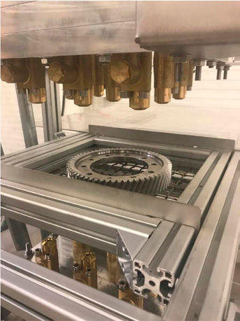
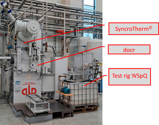
A test rig for WSpQ was designed and built. It can be found in Figure 1. The treated components are first austenitized in a vacuum furnace (SyncroTherm). This furnace can be used for neutral hardening (Ref. 3) as well as for low-pressure carburizing (Ref. 4) of single trays of parts (Ref. 5). This is referred to as single-layer vacuum heat treatment. However, for the development of the WSpQ-process, the parts are not quenched in the vacuum furnace, but the hot parts are manually transferred to the WSpQ-test rig.

Figure 1—Vacuum furnace (SyncroTherm) and test rig for WSpQ.

The test rig for WSpQ consists of two nozzle fields, which are positioned above and below the parts to be quenched, see Figure 2. The nozzle fields—consisting of nine nozzles each—can be independently adjusted in terms of:

  • distance between nozzles and parts to be quenched,
  • flow rate of water,
  • flow rate of compressed air.
Figure 2—Test rig for WSpQ, providing a nozzle system positioned above and below the parts to be quenched.
Share and save:


This article appeared in the March/April 2026 issue.


Read PDF

[advertisement]

In the test rig, water is circulated in a closed loop. No losses due to steam formation or similar effects were observed.

The tray size of this test rig is one-quarter that of the SyncroTherm furnace. The decision was made not to construct the test rig at full scale to reduce the initial financial investment for the development works.

Results

A series of tests was performed on several specimen and gear components made from various steel grades.

Hardness

Figure 3 shows the hardness uniformity of a bolt made of 18CrNiMo7-6 (d = 50 mm, l = 100 mm, m = 1.5 kg) after WSpQ, measured across its cross-section along two measurement lines positioned at a 90-degree angle to each other.

Figure 3—Hardness uniformity through a bolt made of 18CrNiMo7-6 (d = 50 mm, l = 100 mm, m = 1.5 kg) after WSpQ.

The WSpQ-process provided a complete through-hardening of the bolt.

Three different gear-components were quenched using WSpQ. A small gear made of 20MnCr5, a final drive ring gear made of 20MnCr5 and an internal ring gear made of 18CrNiMo7-6 were treated.

Figure 4 shows the achieved core hardness values, demonstrating the very high quench intensity of the process.

Figure 4—Core hardness values (HV) of three different types of gears after quenching with WSpQ.

Cooling Speed

Two bolts with diameters of 25 mm and 40 mm were equipped with thermocouples positioned at depths of 3 mm, 7 mm, and 12 mm to measure cooling curves during the quenching process.

A portable data logging system was used to measure the cooling curves. The bolts were quenched from 930°C, applying WSpQ.

Within just 28 seconds, the bolt with d = 25 mm is fully cooled down to below 100°C, which demonstrates again the very high quenching intensity of the process.

[advertisement]

Furthermore, a numerical model was used to calculate the heat transfer coefficient (HTC) based on the measured cooling curves. For this purpose, the cooling behavior was analyzed in the temperature range between 900°C and 150°C. HTC values of up to 4,000 W/(m²K) were determined for the WSpQ-process, significantly exceeding those of oil quenching (1,500–2,500 W/(m²K)) and helium-gas quenching (1,000–1,500 W/(m²K)).

Surface Appearance and Microstructure

After treatment with WSpQ, the components exhibited a smooth but slightly grey surface appearance. No intergranular oxidation (IGO) was detected. Furthermore, no scaling, decarburization, or other surface defects could be found. The case hardening depth (CHD) turned out as expected. Figure 6 shows the microstructure of a bolt (D = 25 mm, L = 100 mm) made of 20NiCrMo2 after WSpQ. The surface exhibits a fully martensitic structure (100 percent martensite), while the core microstructure consists of a mixture of ferrite, pearlite, bainite, and martensite.

Figure 5—Cooling curves of bolts with d= 25 mm and d=40 mm measured at depths of 3 mm and 12 mm from the surface during quenching with WSpQ.
Figure 6—Surface microstructure after quenching with WSpQ (bolt with D = 25 mm and L = 100 mm made of 20NiCrMo2-material, etching with 3 percent Nittal-solution).

Conclusion and Future Work

WSpQ has proven to be an effective method for intensive quenching. This process offers heat transfer coefficients (HTC) of up to 4,000 W/(m²K), which is significantly higher than those attained with conventional oil quenching methods (1,500–2,500 W/(m²K)).

Furthermore, compared to oil quenching, WSpQ eliminates the Leidenfrost effect, ensuring that the high HTC remains constant throughout the complete quenching process.

The combination of WSpQ with single-layer heat treatment enables, for the first time, the successful application of WSpQ to the treatment of complex-shaped components. This approach offers several advantages:

  • Potential material substitution: to enable the use of less alloyed steel grades, leading to cost reduction.
  • Improved quality after quenching: by enhancing the mechanical properties of the treated parts, including:
  • increased strength,
  • higher Martensite content,
  • increased residual compressive stresses on the surface of the treated components.

Additionally, the process provides the options for:

  • Tailored quench intensity: adjustable cooling rates to tailor the quench intensity for each specific part-geometry and for each specific hardenability of the steel grade.
  • Dynamic quenching capability: the ability to vary quench intensity throughout the process, such as maintaining a specific temperature level during the quenching-process.

WSpQ is primarily suitable for single-layer (or at most double-layer) treatments, as well as for the treatment of large individual components. Bulk load treatment is possible when arranged in a single-layer configuration.

In future investigations, the distortion of components after WSpQ will be examined, along with their fatigue resistance and residual compressive stresses after heat treatment.

The next stages of development will focus on developing and designing a WSpQ chamber compatible with the SyncroTherm furnace, featuring full batch capacity and an automated transfer from the furnace to the quenching unit.

Further testing will be conducted on the following:

  • bulk loads,
  • individual large components,
  • additional materials, including low-alloy steels, free-cutting steels, and potentially titanium.

References

  1. Specht E. et al, 2003, “Transient Measurement of Heat Transfer in Metal Quenching with Atomized Sprays,” Journal of Materials Processing Technology, 2003.
  2. Hamed M.S., 2013, “Spray Quenching,” chapter of ASM Handbook, Volume 4A: Steel Heat Treating Fundamentals and Processes, pp. 245–251.
  3. Totten G.E. et al, 2013, “Quenching of steel,” chapter of ASM Handbook, Volume 4A: Steel Heat Treating Fundamentals and Processes, pp. 91–158.
  4. Heuer V., 2013, “Low pressure carburizing,” chapter of ASM Handbook, Volume 4A: Steel Heat Treating Fundamentals and Processes, pp. 581–590.
  5. Heuer, V., 2018, “Lean heat treatment for distortion control,” AGMA 18FTM23, ISBN 978-1-64353-026-0.
[advertisement]