Analytical Calculation of the Gear Body Stiffness of Face Gears
Introduction and Motivation
The requirements for gearboxes are constantly growing. Among other factors, driven by the concept of achieving sustainability (Ref. 1) and the increasing requirements of e-Mobility, gearboxes are being designed increasingly for maximum performance. The load distribution in the gear contact is a fundamental quantity in the design phase, which is used to design micro-modifications and to determine lifetime. The load distribution can be calculated numerically with full-contact finite element analysis (FE) or with (semi-) analytical methods. Full FE contact investigations are complex and time-consuming. The tooth contact simulation of a gearbox can easily take several hours or even days. This is the reason why alternative methods have been developed and are worthy of further research. Methods deviating from the full FE contact analysis are often summarized in the literature under the term loaded tooth contact analysis (LTCA). With these, analyses are often possible within seconds to a few minutes. In LTCA, stiffnesses of the gear components (housing, bearings, shafts, gearing, etc.) are determined and assembled in a global system stiffness matrix (Refs. 2–6). Tooth stiffness is an essential component in LTCA. Typically, the tooth stiffness is divided into three parts as shown in Figure 1: a) Tooth deformation (normal, shear, and bending deformation); b) Gear body deformation (Tooth tilting deformation); and c) Contact deformation.
Figure 1—Components of tooth deformation (stiffness) according to Weber and Banaschek (Ref. 7): a) Tooth bending deformation with clamped tooth root; b) Tooth tilting deformation with stiff tooth (gear body deformation); and c) Contact point deformation.Figure 2—Exemplary face gear drive. Pinion in gray and face gear in white. Reprinted from Ref. 8.
A comprehensive review of analytical, hybrid and pure FE methods for tooth stiffness calculation is provided by Marafona et al. (Ref. 9) and Natali et al. (Ref. 10). A basic method for calculating gear body stiffness analytically goes back to Weber and Banaschek (W/B) from 1953 (W/B) (Ref. 7). The theory is widely used (Refs. 9,11–14) and even found its way in standards indirectly through the series development of the tooth stiffness (Refs. 15–17). For the gear body deformation/stiffness, W/B assumes that the tooth is rigid and that the connecting parts of the gear body deform elastically when force is applied. Figure 3a shows the applied contact force P on the tooth at the contact point.
The projection onto the tooth centerline yields the height yp above the tooth root. The moment/force components on the wheel body, therefore, decompose to:
The gear body is represented as a half-plane on which boundary stresses/line loads along the tooth root thickness b are specified. Even though the tooth is stiff, the base surface where the line loads are applied can deform freely. The boundary stresses are intended to reproduce the stress state at the tooth root. Figure 3 shows the boundary loads for bending (b), normal (c), and shear load (d). The loads in Figure 3b–d are used to determine the deformation of the half-plane and the partial work integrals. Summing up and equating the partial work integrals with the work done by the external load P results in the deformation uWB in the direction of engagement. Finally, after extensive analytical solving of the partial work integrals, W/B gives an equation for uWB that is valid for v=0.3:
(4)
Figure 3–Model for determining gear body deformation (stiffness) in the direction of engagement according to Weber and Banaschek (Ref. 7):a) Vector decomposition of the contact force P; b) Linear line load (normal) for representation of the bending moment M ; c) Constant line load(normal) for representation of the pressure force N ; d) Constant line load (shear) for representation of the shear force Q . (Figures adapted fromRef. 18; l = Tooth width.)
The analytical-mechanical approach according to Weber and Banaschek (Ref. 7) shows good agreement with experimental investigations (Refs. 19–23).
Face gear drives are a special type of angular gear unit, in which an involute pinion meshes with a face gear wheel (Refs. 24, 25). The pairing can be helical and with or without center offset. Figure 2 shows an exemplary spur face gear drive configuration without center offset. The pressure angle of the face gear wheel is variable across the tooth width and increases towards the outside radius (Refs. 26, 27). One advantage of face gear drives is that both gearings can be manufactured on conventional cylindrical gear machines, and the contact pattern in the axial direction of the pinion does not need to be adjusted (Ref. 25).
However, the comparison of the gear geometries in Figure 2 leads to the conclusion that the approaches for calculating the gear body stiffness of cylindrical gears cannot represent the deformation state of face gear wheels. Due to the plane shape of the face gear wheel, it is to be expected that the deformation increases in the direction of the outer radius. As a result, the stiffness of the gear body decreases toward the outer radius. This work aims to develop a basic model for calculating the gear body stiffness of face gear wheels based on mechanical analytical approaches.
This article is an abridged version of the presentation of the same name given at the AGMA Fall Technical Meeting 2024 (Ref. 28). For more in-depth information, please refer to the corresponding article.
Development of a Calculation Method for the Gear Body Stiffness of Face Gears
The method developed in this work for calculating the gear body stiffness of face gear wheels works analogously to the method according to W/B. However, plate and disk formulations are used for the calculation to accurately represent the deformation states of the face gear wheel. The cylindrical mechanical plate formulation serves to determine the deformation components perpendicular to the wheel center plane (see the “Out-of-Plane Solution” section). The cylindrical mechanical disk formulation serves to determine the deformation components within the wheel center plane (see the “In-Plane Solution” section). The wheel body is modeled as a flat circular plate/disk with constant thickness. Figure 4a shows the coordinate system and structure of the plate and disk models used in this work. As the face gear wheel is circular, a polar coordinate system (r,θ,z) is appropriate. ro and rh are the outer and hub radii of the face gear wheel. The calculation is performed by specifying various line loads along an arc segment from -&elipson; to &elipson; at a radius rf between the hub and outer radius. To solve the deformation states, the plate/disk must be divided into two areas. The first area (I) extends from the hub radius rh to the radius rf at which the load is specified. The second area (II) extends from rf to the outer radius ro. While Figure 4b–c shows the load specification for the plate (out-of-plane), Figure 4d–e shows the load specification for the disk model (in-plane).
Figure 4—Model proposed in this work to determine the gear body deformation (stiffness) of face gears: a) Coordinate systemand structure of the plate/disk model; b) Constant line load in the z-direction (out-of-plane) of the plate; c) Linear line load inthe z-direction of the plate; d) Constant radial line load in the r-direction of the disk; and e) Constant tangential line load inthe circumferential direction of the disk.
Out-of-Plane Solution
The load cases, normal and bending deformation (Figure 3b–c) according to W/B, are also applied in the plate model. This work uses the Kirchhoff-Love theory. The deformation w in z-direction of a circular plate perpendicular to its middle plane (x-y plane in Figure 4) follows the equation (Refs. 29–31):
(5)
q is the surface load on the plate, which does not exist in the model used in this work. Therefore q(r,θ)=0. K is the plate bending stiffness (Refs. 29–31):
[advertisement]
(6)
Δ is the La-Place Operator in polar coordinates (Refs. 29–31):
(7)
The constitutive equations for the internal forces and moments, as well as the kinematic relations, can be obtained from standard mechanical works (Refs. 29–32). The solution of the biharmonic function ΔΔw=0 can be achieved with the series expansion of the deformation (Refs. 32, 33):
(8)
The series is terminated after j terms. Amongst others, the elementary functions R0, Rn and R'n are specified in Refs. 31–36. For the plate deformation, boundary conditions (BC) at the hub and outer radius, and transition conditions (TC) between the plate areas I and II at rf are necessary. These are (Ref. 37):
Fixed clamping at hub radius: Deformation and its first derivative (slope) equal zero (2 BC)
Free end at outer radius: Shear force and moment equal to zero (2 BC)
Continuity at the transition between areas I and II: Displacement and first (slope) and second derivative (curvature) of the displacement are equal (3 TC)
Balance of forces at the transition between areas I and II with the external loading (1 TC)
All in all, this results in a total of eight conditions that are sufficient to solve the problem for different loads.
Normal Deformation: Constant Line Load from -ε to ε
The normal deformation perpendicular to the gear body is determined with a constant line load (Figure 4b). The biharmonic function ΔΔw=0 is solved using a trigonometric series expansion. Therefore, the constant line load must also be developed in a trigonometric series. The Fourier series expansion is suitable for this (Refs. 38, 39). The plate is loaded along the angle segment -f to f with a constant normal force Fd at the radius rf. The constant line load thus results in:
(9)
The Fourier series development of the constant line load pd is (Ref. 39):
(10)
The Fourier series fd can only be calculated with a finite number of terms j. Since the Fourier series represents an even function, it consists of only one constant term and j cos terms dependent on θ. Figure 5 shows an exemplary ideal line load pd (red) and the corresponding Fourier series expansion (black) in a with j=10 elements and b with j=100 elements. As the number of series terms increases, the Fourier series expansion approaches the ideal constant line load. The upper and lower overshoots of the Fourier series at the step points of constant line load distribution are referred to as Gibbs phenomenon (Refs. 38, 40). These make up about 18 percent of half the step height (Ref. 38).
Figure 5—Fourier series expansion (black) of a constant line load (red); parametrization with pd =1 and f=r/6; and a) Fourier expansion with j=10 and b) Fourier expansion with j=100.
Since the Fourier series of the line load fd does not contain any odd components, these are also omitted in the series approach for the plate deformation:
(11)
Bandera and Strozzi (Ref. 34) solve the plate model with clamped inner and outer radii loaded at an arbitrary radius with a point force. Ciavatti et al. (Ref. 37) solve the plate model with a clamped inner radius and free outer radius loaded at any radius with a point load. With these publications and descriptions above, the transfer to the model used in this work is easily possible.
Bending Deformation: Linear Line Load from -ε to ε
The bending deformation perpendicular to the gear body is determined with a linear line load (Figure 4c). A bending moment Mb is specified for the calculation, analogous to W/B. In contrast to W/B, however, the lever arm is extended by half the plate thickness h since the plate is reduced to its middle plane within the plate model. This results in the moment:
(12)
The extreme values/end values of the linear line load are:
(13)
From the Fourier transformation follows the corresponding series expansion:
(14)
The linear line load is an odd function, which is why the Fourier series fb only contains sin terms depending on ε (Ref. 38). Analogous to Figure 5, Figure 6 shows the linear line load (red) and the Fourier series representation (black). As with the constant line load, the ideal line load is more accurately represented as the number of series elements j increases.
Figure 6—Fourier series expansion (black) of a linear line load (red); parametrization with pb =1 and f=r/6;and a) Fourier expansion with j=10 and b) Fourier expansion with j=100.
Since the Fourier series of the line load fb does not contain any even and constant components, these are also omitted in the series approach for the plate deformation:
(15)
The solution process for determining the missing constants from the boundary and transition conditions works in the same way as the load case with constant line load before.
In-Plane Solution
The plate model from the previous section is not suitable for the deformation components within the gear body plane. These can be determined using a disk model. For this, the stress function φmust also fulfill the biharmonic equation (Refs. 29, 30, 41, 42):
(16)
The generally valid form of the stress function in polar coordinates can be found in standard mechanical literature (Refs. 41, 42). The stress components in the disk follow from the stress function (Ref. 41):
(17)
(18)
(19)
The stress-strain (displacement) relations are given in the literature (Refs. 41, 43–46). The following boundary and transition conditions are sufficient for solving the disk deformation in radial (u) and circumferential (v) directions:
Fixed clamping at hub radius: Deformation in radial (u) and circumferential (v) directions equal zero (2 BC)
Free end at outer radius: Stresses equal to zero (2 BC)
Continuity at the transition between areas I and II: Deformation in radial (u) and circumferential (v) directions are equal (2 TC)
Balance of stresses at the transition between areas I and II in radial (u) and circumferential (v) direction with the external loading (2 TC)
Radial Deformation: Radial Constant Line Load from -ε to ε
In the calculation of the partial deformations according to W/B for cylindrical wheel bodies, the tooth can be loaded in the normal section. The three stresses in Figure 3b–d are therefore sufficient to represent the stress state at the tooth root. The plate and disk models used in this paper can be solved for loading along an angular segment from -ε to ε of constant radius rf, which corresponds to the transverse section cylinder at a face gear wheel. External loading in the normal section plane at the face gear wheel is not straightforward with plate and disk models. In contrast to W/B, a fourth stress component is therefore included in the model to represent the influence of axial force at the contact point (Figure 4d). Analogous to the constant normal line load from “Normal Deformation” section, the constant radial line load follows to:
(20)
For the disk model the Fourier series expansion of the external loading must also be developed into a boundary stress condition. The boundary stress is obtained by dividing the line load p_r by the disk thickness:
(21)
The Fourier series development of the boundary stress is not shown graphically here, as this is analogous to Figure 5. The solution of the disk equations and the determination of the deformations in radial (u) and circumferential (v) direction were developed and described in detail by DuBois (Ref. 47) for a circular disk with radial point load at the outer radius. Furthermore, Serati et al. (Ref. 45) describe the solution for a radially loaded disk. With these and with the description of the BCs and TCs from the “In-Plane Solution” section, the transfer of the solution method for the disk model with areas I and II as well as a distributed constant line load is possible without any problems.
Shear Deformation: Circumferential Constant Line Load from -ε to ε
The shear deformation of the gear body is modeled with a constant shear load at the disk (Figure 4e), analogous to W/B. As with the previous line loads, the constant shear line load along the load path from -<ε to ε is:
(22)
The Fourier series expansion of the shear stress is therefore:
(23)
The deformation is solved analogously to the radial load. Srinivasan and Ramamurti (Ref. 48) describe the solution of a disk with concentrated edge load on the outer radius.
Face Gear Wheel Body Stiffness Calculation
The deformation in the direction of engagement uPD at a radius rf can be determined by balancing the partial work integrals w (Refs. 7, 49) done by the external line loads at the plate/disk against the work from the external force P:
(24)
The partial work integrals are determined from the respective external ideal line loads p and deformations w along the load paths Τ:
(25)
Herein uPD is uWB in Figure 3a for the plate/disk approach. The deformation solutions for normal (d), bending (b), shear (s), and radial load (r) are known from the previous sections. At the contact point, the contact force P must be divided into its components (Figure 3a + the radial component out of the transverse section) and used to determine the partial deformations according to the “Out-of-Plane Solution” and “In-Plane Solutions” sections. The deformations are calculated along the load path from -ε to ε only and the work w resulting from this is determined using the respective ideal line load (red curves in Figure 5 and Figure 6). Determining the work integrals in this way has the advantage that the deformation only must be determined along the load path and not along the entire circumference of 2π. This means that considerably fewer points need to be calculated. The deformation in the direction of engagement and the contact force result in the gear body compliance q'R or the wheel body stiffness c’R:
(26)
Typically, P=1 N is used to obtain the compliance directly. However, due to the linear elasticity theory, any other force P can also be specified.
Results
Table 1 shows the face gear drive parameters used for the following validations. The data has already been used for other investigations on face gear drives (Refs. 18, 50). The macro tooth geometry is shown in Figure 2. The half angle f results from the number of teeth z of the face gear wheel. The load path from -f to f extends over the angular pitch τ:
(27)
Parameter
Symbol
Value
Unit
Face gear teeth number
z
61
-
Face gear hub radius
rh
12.5
mm
Face gear inner radius of the teeth
ri
29.5
mm
Face gear outer radius of the teeth
ro
37.6
mm
Face gear thickness below the teeth
h
6
mm
Normal module
mn
1
mm
Pinion normal pressure angle
αn
20
°
Modulus of elasticity
E
210000
MPa
Poisson ratio
υ
0.3
-
Table 1—Design parameters of the exemplary spur face gear from Figure 2.
The validation of the methods described for calculating plate and disc deformation using the Fourier series approach is included in the conference paper (Ref. 28). In addition, the corresponding conference paper contains an analysis of the influence of the Fourier series parameter j on the convergence of the partial work integrals.
The aim is to develop a method for gear body stiffness for face gear wheels. Using the method from the “Face Gear Wheel Body Stiffness Calculation” section, this is possible along the tooth width (face gear radius). For the calculation, it is necessary to split the force P at the contact point into the individual force components (normal, bending, shear, and radial). Usually, the force components and directions (pressure angle) result from a load-free tooth contact simulation. For spur face gear drives (β=0), the pressure angle can also be approached from the model of the curved gear rack (Refs. 26, 27):
(28)
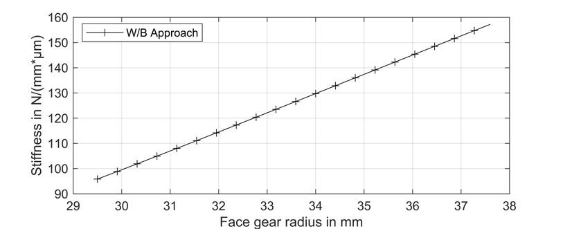
Herein, mn is the normal module, z is the face gear teeth number, and an is the normal pressure angle of the pinion/cutter. The relationship thus gives the face gear pressure angle along the tooth width (radius r). The force/moment components result from the equations according to W/B in the “Introduction and Motivation” section. The radial force component is zero for spur face gears (Ref. 51). The W/B approach is essentially a 2D model of a plane with different loads on the boundary. To determine the stiffness across the tooth width with variable pressure angle, the gear tooth is divided into single slices (thin-slice model). With the previous equation, it is obvious that the pressure angle α' increases over the face gear tooth width. W/B applied to each single slice results in the gear body stiffness curve in Figure 7. The stiffness curve shows almost linear behavior. Due to the slice model, the stiffness is related to the slice thickness and given per unit face width. The unit N/(mm*μm) is chosen according to ISO 6336 (Ref. 16). The stiffness for the slice model is normalized to the slice thickness, as it changes with the thickness. Due to normalization, the curve in Figure 7 is independent of the number of slices (slice thickness). Figure 7 clearly shows that—when the method according to W/B is applied directly—the gear body stiffness increases along the tooth width. The deviation of the stiffness between the outer and inner radius for the W/B approach is:
(29)
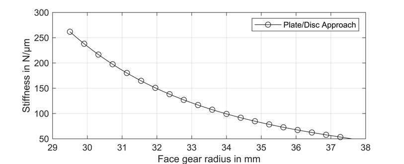
Figure 7—Gear body Stiffness along the face gear radius (tooth width), derived using the W/B method in single slices (yp =1 mm ). Tooth root width for W/B b=2frf.Figure 8—Gear body Stiffness along the face gear radius (tooth width), derived using the proposed method in this work (yp =1 mm).
Figure 8 shows the gear body stiffness curve along the tooth width, determined using the method proposed in this work. Since the plate/disk approach is no longer a thin-slice model and the gear body stiffness is determined on the full model for discrete radii between the inner and outer radius of the teeth, the stiffness cannot be normalized to the slice thickness. This results in the unit N/μm. A qualitative comparison with the W/B method is therefore possible. In contrast to the W/B method in Figure 7, the gear body stiffness curve in Figure 8 shows a decreasing behavior. It is also evident that the curve does not show linear growth. The deviation of the stiffness between the outer and inner radius for the plate/disk approach is:
(30)
Discussion
The cylindrical plate and disk models with constant thickness approximate the real geometry of the face gear wheel. In reality, the gear bodies can be more complex in shape or can have a non-constant thickness along the radius. Especially at the hub, the thickness may be higher. However, particularly concerning the W/B method in the “Introduction and Motivation” section, in which the gear body of cylindrical gears is approximated as an infinite half-plane, the assumption of a circular plate/disk with constant thickness seems justified.
One advantage of the analytical formulation is that deformations can be calculated independently of any mesh discretization. For work integrals, only the deformations along the load paths are relevant and need to be determined beforehand. This is possible with the analytical models. With FE methods, on the other hand, complete models must be solved. To apply the loads and reliably calculate the deformations, meshing must be appropriately fine around the loads in the FE method. Modeling and calculation time with the FE method is therefore significantly higher compared to the analytical approach. The analytical method mainly requires one-off work in developing the deformation equations.
The work integrals from the analytical deformation calculations yield the gear body stiffness at the contact point. In contrast to the developed method (Figure 8), the gear body stiffness increases along the tooth width for the conventional approach with the infinite half-plane in Figure 7. However, it must be noted that this approach was never developed for face gear wheels, but for cylindrical gears (Ref. 7). It just makes sense to use existing, established methods as a first try. One explanation for the increase in stiffness could be the deformation component of the normal force. With increasing radius, the face gear pressure angle α' and therefore the normal force increases. In the conventional approach, the work integral of the normal force (Figure 3c) is determined through a comparison approach (Ref. 7). In addition, it is already mentioned in the work that the influence of the normal force component will be subordinate (Ref. 7). This is certainly an appropriate assumption for cylindrical gears where the full material gear body is supported by a shaft at the hub but does not apply to face gear wheels. Due to the greater leverage with a larger radius, gear body stiffness should decrease along the tooth width. With the investigation in the “Results” section, it is obvious that the developed approach in this work shows the intended gear body stiffness behavior of face gear wheels (Figure 8).
The aim is to first develop a model to determine the face gear body stiffness. For validation, the calculation at one point in the profile direction for several slices in width was chosen, as the main change in stiffness is expected in the width. Nevertheless, the approach can also be used to determine stiffness in profile direction (time-dependent or as a function of the roll angle). For this purpose, the parameters yP and α' must be chosen accordingly. These usually result from a load-free tooth contact analysis, which is not part of this work.
The calculation is based on an analytical material model. Non-linear behavior (e.g., for plastic) cannot be calculated directly. The analytical derivation is already complex, which would be enormously increased by using non-linear material behavior. Nevertheless, plastics can be represented in good approximation using adapted material parameters (modulus of elasticity and Poisson’s ratio).
The load cases are not coupled in the analytical models. The in-plane and out-of-plane solutions are derived separately. This is certainly an assumption that must be made to enable analytical calculation. Analytical models for calculating the coupled loading/deformation are—to the best of the authors’ knowledge—not available. The focus of this work is on fast analytical calculation. Coupled loading is possible with numerical models, but this increases the complexity and calculation time. However, the uncoupled analytical approach shows the expected behavior.
Conclusion and Outlook
Face gear drives are angular gear units, in which an involute pinion meshes with a face gear wheel. While the pinion is a cylindrical gear, the face gear wheel is disk-shaped. Conventional approaches for calculating gear body stiffness focus on cylindrical gears. The most accurate stiffness calculation is a prerequisite for the LTCA—apart from the full FE contact calculation—to determine valid results. This paper presents an analytical method for the gear body stiffness of face gear wheels based on an established approach in the “Development of a Calculation Method for the Gear Body Stiffness of Face Gears” section. The face gear wheel serves as a demonstration object. However, the approach can be directly transferred to other plate-shaped gears without great effort. The “Results” section confirms the developed model.
Different points can be mentioned as an outlook. The Kirchhoff-Love plate theory is applied to the out-of-plane deformation. An extension of the proposed method could be the use of a more advanced plate model, which takes shear deformation into account (Ref. 52). Higher-order plate formulations, such as the Reissner model, are described with a system of differential equations (Ref. 29). This makes the solution process much more complex, which is why the Kirchhoff-Love model was used in this work at first.
A further development of the proposed approach could be the incorporation of the stiffening effects of the gear teeth or the hub. Since the analytical plate/disk model in its current development stage only allows for constant thickness, FE-reference calculations could be used to derive a stiffness factor along the tooth width for various complex gear body shapes.
The paper developed and validated the basic approach for the gear body stiffness of disk-shaped gears. Further work will focus on the LTCA of face gear drives. The stiffness in the profile and width direction will be determined using the presented approach. It is expected that the load distribution over the flanks in meshing will change accordingly. One central aspect is the conversion of the plate/disk gear body stiffness formulation to a slice stiffness formulation, as used in LTCA.
Acknowledgements
The presented results are based on the research project AZ-1601-23 supported by the Bavarian Research Foundation (Bayerische Forschungsstiftung, BFS). The authors would like to thank for the sponsorship and support received from the BFS.
References
Anastas P. T., and Zimmerman J. B., 2003, “Design through the 12 principles of green engineering,” Environmental Science & Technology, Vol. 37, No. 5, pp. 94A–101A. doi:10.1021/es032373g.
Neubauer B., Otto M., and Stahl K., 2015, “Efficient Calculation of Load Distribution and Design of Tooth Flank Modifications in Planetary Gear Systems: Static load and deformation analysis in a fully coupled mechanical model of a gear box structure with LAPLASn,” International Conference on Gears 2015, VDI-Verl., Düsseldorf, pp. 549–558.
Weinberger U., Otto M., and Stahl K., 2020, “Closed-Form Calculation of Lead Flank Modification Proposal for Spur and Helical Gear Stages,” ASME. J. Mech. Des, Vol. 142, No. 3. doi:10.1115/1.4045396.
Wu S.-H., and TSAI S.-J., 2009, “Contact stress analysis of skew conical involute gear drives in approximate line contact,” Mechanism and Machine Theory, Vol. 44, No. 9, pp. 1658–1676. doi:10.1016/j.mechmachtheory.2009.01.010.
Placzek T., 1988, “Lastverteilung und Flankenkorrektur in gerad- und schrägverzahnten Stirnradstufen,” Dissertation, Technische Universität München.
Winter H., and Placzek T., 1991, “Load Distribution and Topological Flank Modification of Helical and Double Helical Gears,” Eur. J. Mech. Eng., Vol. 36, No. 3, pp. 171–176.
Weber C., and Banaschek K., 1953. Formänderung und Profilrücknahme bei gerad- und schrägverzahnten Rädern, 1st ed., Friedrich Vieweg & Sohn, Braunschweig.
Hochrein J.-F., Otto M., and Stahl K., 2024, “Face gear drives: Nominal contact stress calculation for flank load carrying capacity evaluation,” Mechanism and Machine Theory, Vol. 195. doi:10.1016/j.mechmachtheory.2024.105573.
Marafona J. D., Marques P. M., Martins R. C., and Seabra J. H., 2021, “Mesh stiffness models for cylindrical gears: A detailed review,” Mechanism and Machine Theory, Vol. 166. doi:10.1016/j.mechmachtheory.2021.104472.
Natali C., Battarra M., Dalpiaz G., and Mucchi E., 2021, “A critical review on FE-based methods for mesh stiffness estimation in spur gears,” Mechanism and Machine Theory, Vol. 161. doi:10.1016/j.mechmachtheory.2021.104319.
Spura C., and Berger G., 2011, “Ermittlung des Verformungs- und Steifigkeitsverhaltens von bombierten Profilwellenverbindungen mit Evolventenverzahnung,” Forsch Ingenieurwes, Vol. 75, pp. 35–44. doi:10.1007/s10010-011-0132-9.
Spura C., 2015, “Berechnung der Verformungen und Steifigkeiten evolventischer Verzahnungen von Zahnkupplungen,” Forsch Ingenieurwes, Vol. 79, pp. 5–15. doi:10.1007/s10010-015-0183-4.
Petersen D., 1989, “Auswirkungen der Lastverteilung auf die Zahnfußtragfähigkeit von hoch überdeckenden Stirnradpaarungen,” Dissertation, Technische Universität Braunschweig.
Schäfer S., 1971, “Ein Beitrag zur Ermittlung des wirksamen Flankenrichtungsfehlers bei Stirnradgetrieben und der Lastverteilung bei Geradverzahnung,” Dissertation, Technische Hochschule Darmstadt.
ISO 6336-1:2019-11, 2019, “Calculation of load capacity of spur and helical gears—Part 1: Basic principles, introduction and general influence factors.”
DIN 3990-1:1987-12, 1987, “Tragfähigkeitsberechnung von Stirnrädern—Einführung und allgemeine Einflußfaktoren.”
Hochrein J.-F., Otto M., and Stahl K., 2022, “Fast tooth deflection calculation method and its validation,” Forsch Ingenieurwes, Vol. 86, pp. 845–859. doi:10.1007/s10010-022-00598-8.
Daffner M., 2018, “Validierung von Verformungsberechnungen im System Zahnrad-Welle-Lager-Gehäuse,” Dissertation, Technische Universität München.
Winter H., and Podlesnik B., 1983, “Zahnfedersteifigkeit von Stirnradpaarungen Teil 1: Grundlagen und bisherige Untersuchungen,” Antriebstechnik, Vol. 22, pp. 39–42.
Winter H., and Podlesnik B., 1983, “Zahnfedersteifigkeit von Stirnradpaarungen Teil 2: Einfluss von Verzahnungsdaten, Radkörpern, Linienlast und Wellen-Naben-Verbindung,” Antriebstechnik, Vol. 22, pp. 51–58.
Winter H., and Podlesnik B., 1984, “Zahnfedersteifigkeit von Stirnradpaarungen Teil 3: Einfluss der Radkörperform auf die Verteilung der Einzelfedersteifigkeit und der Zahnkraft längs der Zahnbreite,” Antriebstechnik, Vol. 23, pp. 43–49.
Daffner M., Otto M., and Stahl K., 2017, “Method of measuring the load distribution of spur gear stages,” JAMDSM, Vol. 11, No. 6. doi:10.1299/jamdsm.2017jamdsm0076.
Litvin F. L., and Fuentes A., 2004. Gear Geometry and Applied Theory, 2nd ed., Cambridge University Press. doi:10.1017/CBO9780511547126.
Basstein G., and Sijtstra A., 1993, “Neue Entwicklungen bei Auslegung und Fertigung von Kronenrädern,” Antriebstechnik, Vol. 32, No. 11, pp. 53–60.
Basstein G., and Sijtstra A., 1993. “New developments in Design, Manufacturing and Application of Cylkro-(Face) Gears,” AGMA technical paper 93FTM7, American Gear Manufacturers Association, Alexandria, Virginia.
Berger J.-F., Otto M., and Stahl K., 2024. “Analytical Calculation of the Gear Body Stiffness of Face Gears,” AGMA technical paper 24FTM08, American Gear Manufacturers Association, Alexandria, Virginia.
Altenbach H., Altenbach J., and Naumenko K., 2016. Ebene Flächentragwerke: Grundlagen der Modellierung und Berechnung von Scheiben und Platten, Springer Berlin Heidelberg, Berlin, Heidelberg. doi:10.1007/978-3-662-47230-9.
Girkmann K., 1963. Flächentragwerke, Springer Vienna, Vienna. doi:10.1007/978-3-7091-8096-9.
Föppl A., 1912, “Die Biegung einer kreisförmigen Platte,” Sitzungsberichte der mathematisch-naturwissenschaftlichen Abteilung der Bayerischen Akademie der Wissenschaften zu München(II), pp. 155–190.
Timoschenko S. P., and Woinowsky-Krieger S., 1959. Theory of Plates and Shells, 2nd ed., McGraw-Hill, New York.
Reißner H., 1929, “Über die unsymmetrische Biegung dünner Kreisringplatten,” Ing. arch, Vol. 1, pp. 72–83. doi:10.1007/BF02079709.
Bandera C., and Strozzi A., 1991, “Displacements in a clamped annular plate transversely loaded at an arbitrary point by a concentrated force,” International Journal of Pressure Vessels and Piping, Vol. 49, No. 1, pp. 17–34. doi:10.1016/0308-0161(92)90070-V.
Strozzi A., 1989, “Mechanical analysis of an annular plate subject to a transverse concentrated load,” The Journal of Strain Analysis for Engineering Design, Vol. 24, No. 3, pp. 139–149. doi:10.1243/03093247V243139.
Dragoni E., and Strozzi A., 1989, “Mechanical analysis of a simply supported annular plate loaded by a periphery force,” International Journal of Pressure Vessels and Piping, Vol. 40, No. 3, pp. 175–191. doi:10.1016/0308-0161(89)90103-8.
Ciavatti V., Dragoni E., and Strozzi A., 1992, “Mechanical Analysis of an Annular Plate Transversely Loaded at an Arbitrary Point by a Concentrated Force,” Journal of Mechanical Design, Vol. 114, No. 3, pp. 335–342. doi:10.1115/1.2926558.
Karpfinger C., 2022. Calculus and Linear Algebra in Recipes, Springer Berlin Heidelberg, Berlin, Heidelberg. doi:10.1007/978-3-662-65458-3.
Márkus G., 1985. Kreis- und Kreisringplatten unter periodischer Belastung, 1st ed., Werner, Düsseldorf.
Carslaw H. S., 1921. Introduction to the Theory of Fourier’s Series and Integrals and the Mathematical Theory of the Conduction of Heat, 2nd ed., Macmillan, London.
Timoschenko S. P., and Goodier J. N., 1951. Theory of Elasticity, 2nd ed., McGraw-Hill, New York.
Michell J. H., 1899, “On the Direct Determination of Stress in an Elastic Solid, with application to the Theory of Plates,” Proceedings of the London Mathematical Society, Vol. s1-31, No. 1, pp. 100–124. doi:10.1112/plms/s1-31.1.100.
Boresi A. P., Chong K. P., and Lee J. D., Eds., 2010. Elasticity in Engineering Mechanics, Wiley. doi:10.1002/9780470950005.
Sadd M. H., 2014. Elasticity: Theory, Applications, and Numerics, 3rd ed., Elsevier. doi:10.1016/C2012-0-06981-5.
Serati M., Alehossein H., and Williams D. J., 2012, “Elastic stress analysis of partially loaded hollow discs,” International Journal of Engineering Science, Vol. 53, pp. 19–37. doi:10.1016/j.ijengsci.2011.12.010.
Biezeno C. B., and Grammel R., 1953. Technische Dynamik, 2nd ed., Springer Berlin Heidelberg, Berlin, Heidelberg. doi:10.1007/978-3-642-65187-8.
DuBois R. P., 1970, “Buckling loads of tensioned circular plates subject to concentrated in-plane loading,” Master’s thesis, Kansas State University, http://hdl.handle.net/2097/7439.
Srinivasan V., and Ramamurti V., 1980, “Stability and vibration of an annular plate with concentrated edge load,” Computers & Structures, Vol. 12, No. 1, pp. 119–129. doi:10.1016/0045-7949(80)90100-5.
Hochrein J.-F., Güntner C., Otto M., and Stahl K., 2024, “Face gear drive manufacturing: Pinion/cutter design for a crowned contact pattern,” Proceedings of the Institution of Mechanical Engineers,Part B: Journal of Engineering Manufacture, Vol. 238, No. 9, pp. 1282–1292. doi:10.1177/09544054231196597.
Tsai S.-J., 1997, “Vereinheitlichtes System evolventischer Zahnräder: Auslegung von Zylindrischen, Konischen, Kronen- und Torusrädern,” Dissertation, Technische Universität Braunschweig.