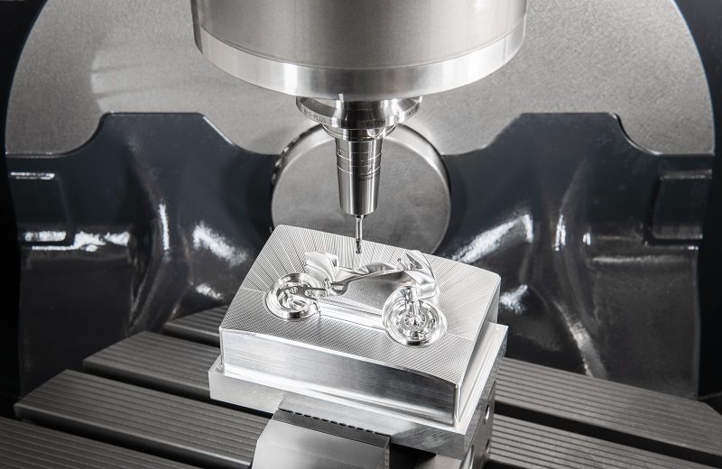
Machining at higher speeds can save time and money. But like driving down the highway, increasing the speed means increasing the inherent risk.
A tool holder rotating at 35,000 rpm poses more danger than the same tool holder rotating at 8,000 rpm, based on kinetic energy alone. If a high-speed operation goes awry, there isn’t much time to act, and typically the part, workholding or machine bears the brunt of the damage, not to mention potential danger to the operator.
Nevertheless, with great risk comes great reward, and those who master machining at high speeds quickly reap the benefits of increased productivity. If necessity demands running at higher speeds, choose the proper tooling and cutting strategies or you may be doomed from the start.
Spindle speed and balance
The first step is knowing the maximum speed of your spindle. This is the absolute ceiling when it comes to speed.
The next inclination is to look at the cutting tool. This means trading in high-speed steel tools for carbide, or carbide for super hard materials like PCD or CBN. Increasingly hard cutting tools largely translate to increasingly fast cutting speeds, and today’s modern cutting geometry designs have made possible previously unthinkable speeds.
But many ignore the interface between the two: the tool holder.
Machining speed, besides depending on the physical limitations of the machine tool and cutting tool, will largely be governed on how well balanced the tool holder is. Balance is usually the focus when talking about high-speed tool holders because it offers the greatest opportunity for improvement, but keep in mind the maximum speed will only be as fast as the “weakest link” allows. If you have a 12,000 rpm spindle, inserts that allow cutting at 9,000 rpm, but the tool holder is only balanced for 8,000 rpm, then 8,000 is the max rpm.
The faster you spin, the more exaggerated mass irregularities become, and speed harmonics present in the system will become increasingly excited. This translates into vibrations which, in turn, cause poor runout, surface finish, scrapped parts and equipment damage. Symmetry is your best friend at high speeds.
Shrink fit holders, hydraulic chucks and high-performance collet chucks are typically the best examples of well-balanced tool holders because, by design, they’re symmetrical. They’re also generally slim – most of the mass is concentrated near their centerline.
Balancing act
When it comes to fine boring tools, balancing can be a serious issue. Single-point finish boring heads are fundamentally unbalanced because of asymmetry, and special care is required to ensure they perform as expected. To say bores are tolerance-sensitive is an understatement; this unbalance can easily scrap a part.
Running a boring head as fast as it can go should always be the goal, however, unbalance can be introduced to the system. An unbalanced boring head can be deceptive because it will frequently bore your diameter within spec. Yet, upon further inspection, you will find an oval-shaped bore rather than a circle-shaped one.
Circularity/cylindricity is a common GD&T (geometric dimensioning and tolerancing) callout for shafts and holes, so boring head balance is crucial for those situations. At the very least, standard boring heads are usually pre-balanced for a diameter somewhat near the middle of their diameter range. If it’s a rigid, reasonably short bore, this will suffice.
When higher speeds and longer boring bars are needed, consider auto-balancing heads. These heads are well-balanced throughout their diameter range; the head that automatically adjusts a counterweight as the diameter is adjusted.
Taper considerations

Equally important as the tool holder body is the taper. In most cases, you’re stuck with the machine spindle taper you have. But, if contemplating a new machine, consider one with an HSK spindle.
HSK combats problems that conventional steep tapers encounter at high speeds. The spindle taper expands more than the holder under high centrifugal force because of differences in stiffness, which causes the tool to “sink” in the Z-axis. The drawbar fingers go inside of the thin-walled taper and expand outward to clamp. Unlike steep tapers, high speeds aid the clamping mechanism and proper seating.
HSK holders have flange contact in addition to taper contact as part of the standard. This eliminates the dreaded sinking phenomenon. Past 35,000-40,000 rpm, an HSK spindle becomes one of the only options.
Additionally, alleviate unwanted Z-axis movement with BIG-PLUS tooling, which is the same flange contact principle applied to steep taper holders like CAT or BT. You also will see huge gains in rigidity, given you have a BIG-PLUS spindle.
Exploring a new frontier

Ideally, keep the mass of the tool holder as close to the centerline of rotation as possible, and keep the tool as short as possible. This is the reason why there is general trend of higher maximum speed the smaller the tool holder is. You simply don’t have much mass to throw around, so a higher speed can be attained safely. HSK-E style tool holders take this principle to the extreme.
In addition to having an HSK taper that’s well-suited to higher speeds, it aims to be as close to perfectly symmetrical as possible by the removal of notches and drive key slots. These are commonly used in conjunction with very small diameter tools in order to reach ridiculously fast speeds. It’s not unheard of to achieve upwards of 50,000 rpm in some applications. The only catch is you are using very small tools.
Again, when it comes to tool holders, the max speed largely depends on balance. A high-speed machinist will be well-acquainted with the fickle art of balancing tool holders and the standards that are used. As tooling technology and speed progress, so too does the need for a proper standard by which to measure unbalance.
Future impact
The tendency in machining has been toward faster and faster, and there’s no reason to believe this trend will change anytime soon.
Developments in 3D printing technology, hybrid processes, and rapid digitalization and interconnectivity will greatly impact the manufacturing sector. There will be a push toward high-speed machining to complement and keep up with these processes.
Shops are in a constant race with each other, and those who don’t adapt easily to the constant advances in technology are left in the dust. With higher speeds becoming more of a necessity, proper understanding and implementation of these strategies is essential to survival.
About the Author:
Jack Kerlin is an applications engineer at BIG DAISHOWA Inc. (formerly BIG KASIER Precision Tooling). He can be reached at (224) 770-2937 or jack.kerlin@us.bigdaishowa.com. For more information, visit bigdaishowa.com


